3 The Touch-Screen
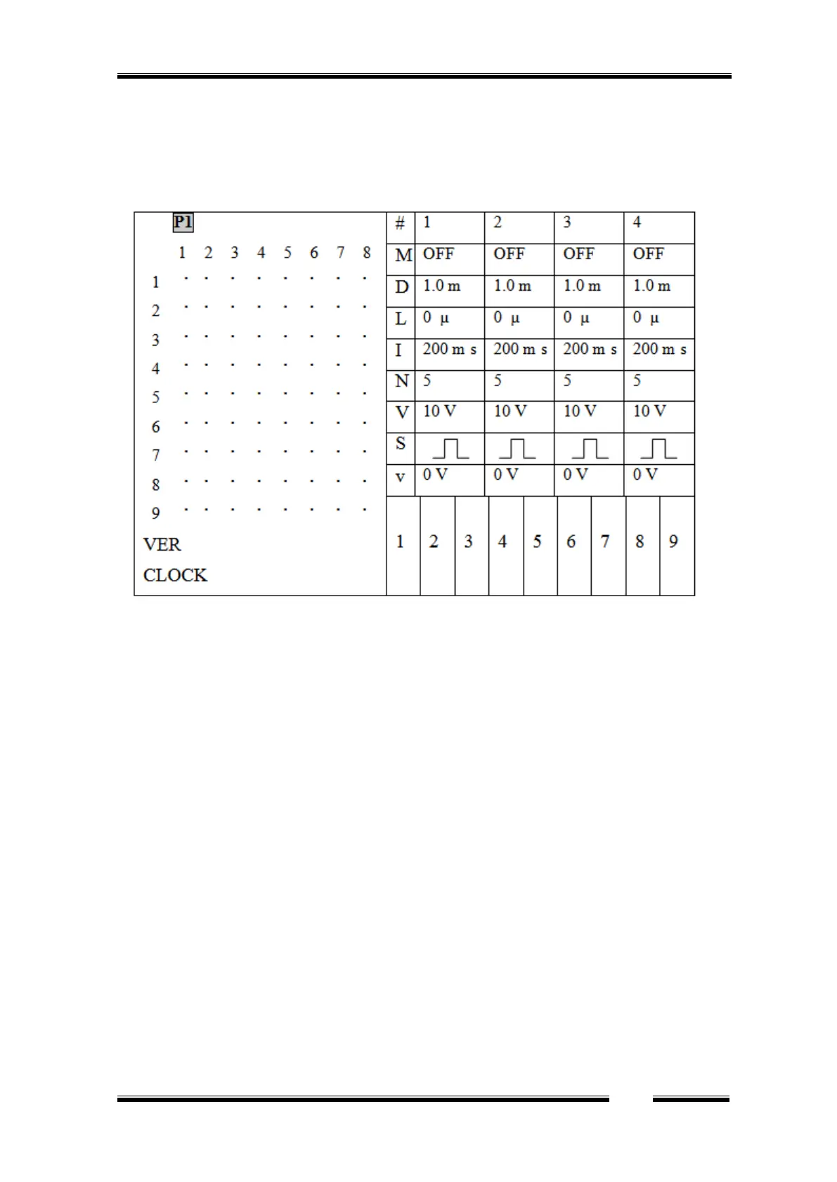
When the Master-9 is turned on, the following screen is displayed:
Figure 2
3.1 The parameters of the channels
The screen is divided vertically:
The right side of the screen displays the parameters of channels 1, 2, 3 and 4.
The definition column is displayed to the left of channel 1. This definition column defines the
heading of each row, as follows:
1. # - The top row shows the channel number.
2. M -Mode: The 2
nd
row defines the channel operating mode (see Chapter 4).
3. D - Duration: The 3
rd
row defines the pulse duration (see Chapter 5, figure 3) - the time that
elapses from the onset of the output pulse to its end.
4. L – deLay: The 4
th
row defines the delay time - the time that elapses from the beginning of
the input trigger to the beginning of the output pulse.
5. Interval: The 5
th
row defines the Interval time - the time that elapses between the beginning
of a pulse and the beginning of the following pulse (interval = 1/rate).
6. N – Number: The 6
th
row defines the number of pulses per train in the TRAIN mode.
7. V – Volt: The 7
th
row defines the pulse amplitude in volts.
8. S – Shape: The 8
th
row defines the shape of the pulse: Monopolar, Bipolar or Ramp.
9. v – ΔV: The 9
th
row defines the ΔV increment or decrement voltage steps, if applied.
Example: In Figure 2 above you see that each of the channels (1, 2, 3, 4) is in its default values as
follows: Set to OFF mode, duration time is set to D=1.0 msec. Delay time is set to L=0 µsec,
 Loading...