OPERATION & SERVICE
Servicing should only be performed by a Qualified Service Agent
54
Checking Power and Ground To The CCB
The CCB is powered by the120 VAC Control Circuit Transformer (see pages 39 - 41) at the
J2 Socket, pins 1 & 3 (see page 50). This procedure is performed to ensure the 120 VAC
power is being supplied to the CCB.
1 Ensure the main breaker or disconnect switch is turned on.
2 Verify with an AC volt meter that proper voltage is present at the Power Distribution Block or the contactor
on single element models (see Figures 1 and 2 on pages 8 & 9 and pages 12 - 14).
3 Using an AC volt meter; set the volt meter to an AC voltage range just above 120 VAC.
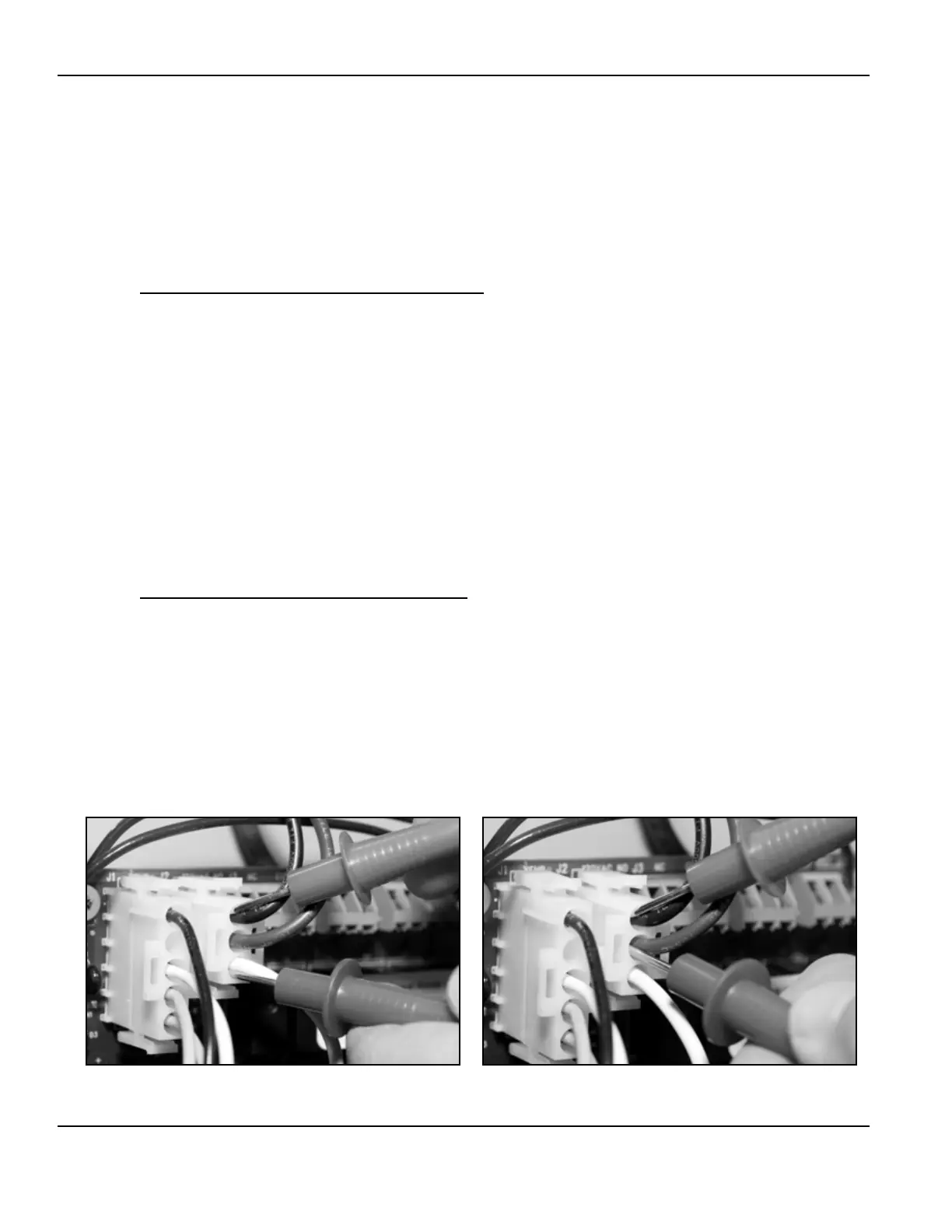
4 Ensure 120 VAC power is supplied to the CCB.
With the J2 plug installed in the J2 socket on the CCB
(page 50) insert the two volt meter probes into pins 1 & 3 of J2 plug as shown in the “Checking for 120
VAC” image below. Volt meter probes may have to be pressed firmly into the plug to make contact with the
metal conductors inside. Voltage should be approximately 120 VAC.
5 If the measured voltage is approximately 120 VAC the CCB is receiving the correct power.
6 If the measured voltage is zero volts or considerably less than 120 VAC:
• Check the 120 VAC wiring between the CCB J2 socket and the 120 VAC Control Circuit Transformer
- ensure wiring is correct and connections are tight and making good contact.
• Check the J2 plug/socket connections on the CCB for wear or damage. Ensure they are mating
properly and providing good contact - see page 50.
• Check the 120 VAC Control Circuit Transformer to ensure it is wired correctly and outputting the
correct voltage - see pages 39 - 41.
• Check the Control Circuit fuses - see Figures 1 and 2 on pages 8 & 9 for location and the Fuse test
procedure on page 15.
7 Ensure earth ground is supplied to the CCB.
With the J2 plug installed in the J2 socket on the CCB
(page 50) insert the two volt meter probes into pins 1 & 2 of the J2 plug as shown in the “Checking for
Ground” image below. Volt meter probes may have to be pressed firmly into the plug to make contact with
the metal conductors inside. If the measured voltage is approximately 120 VAC the CCB is properly
grounded.
8 If the measured voltage is zero volts or considerably less than 120 VAC:
• Check the ground wiring between the CCB J2 socket and the water heater’s ground connection -
ensure wiring is correct and connections are tight and making good contact.
• Ensure the water heater is properly grounded.
Checking for 120 VAC Checking for Ground
 Loading...