8 100271597
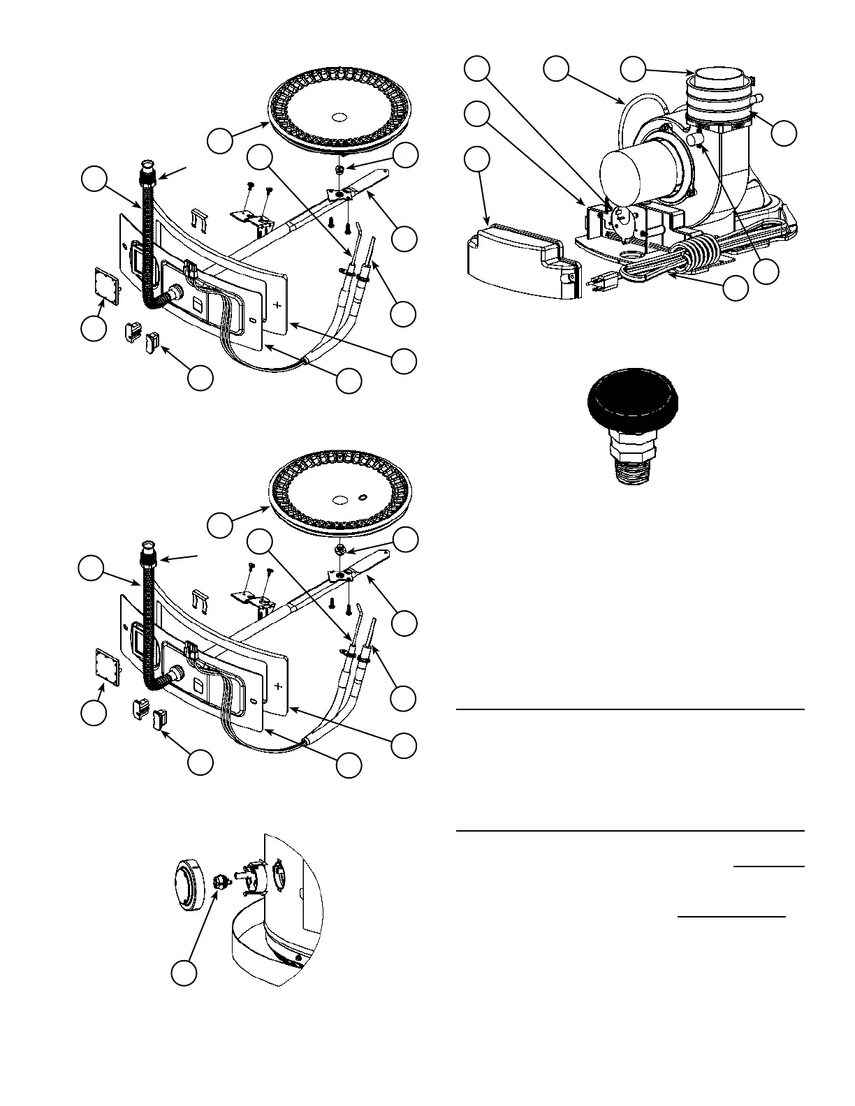
Natural gas main burner
with igniter assembly
(item 17 in Figure 1).
Flare
Nut
42
44
40
37
39
41
38
45
43
21
Figure 3
Propane (LP) main burner
with igniter assembly
(item 17 in Figure 1).
Flare
Nut
42
44
40
46
39
41
38
45
43
21
Figure 4
20
Figure 5
50
6
49
28
29
4847
51
Figure 6
Vacuum relief valve
install per local
codes (not supplied
with heater).
Figure 7
Notes:
* Items not supplied with the water heater.
** The side recirculation loop connections may not be
used as the primary water inlet and outlet connections.
See “Combo Heating Inlet And Outlet Side Taps”.
*** Caution: harness has 120 VAC In operation.
**** See “Planning The Vent System”, “Condensate” and
“Blower Assembly Installation” for more information.
REPLACEMENT PARTS AND DELIMING PRODUCTS
Replacement parts and recommended delimer may be
ordered through authorized servicers or distributors. When
ordering parts, provide complete model and serial numbers
(see rating plate), quantity and name of part desired.
Standard hardware items may be purchased locally.
COMBO HEATING INLET AND OUTLET SIDE TAPS
Models equipped with Combo Heating capabilities are
shipped with the two side plumbing taps PLUGGED
(item 8 and item 13 in Figure 1 and see also Figure 8 &
Figure 22). If the heater is to be operated using the side
taps for combo heating, these taps must be opened by
removing the two pipe plugs .
 Loading...