Do you have a question about the A.O. Smith T-H3J-DV and is the answer not in the manual?
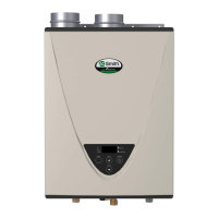
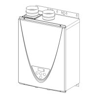
Visual representation of the unit's external features and connection points for direct vent indoor models.
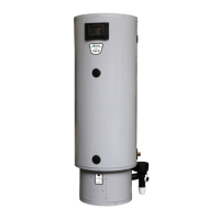
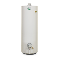
Visual representation of the unit's external features and connection points for outdoor models.
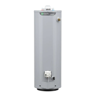
Diagram showing internal components for 240/340 indoor models.
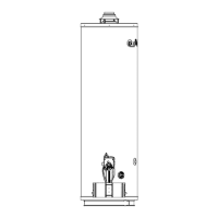
Diagram showing internal components for 240/340 outdoor models.
Diagram showing internal components for 540 indoor models.
Diagram showing internal components for 540 outdoor models.
Electrical wiring schematic for 240/340 models.
Electrical wiring schematic for 540 models.
Specific electrical check points for diagnosing wiring issues.
Further electrical check points for diagnosing wiring issues.
Resistance data for temperature thermistors at various temperatures.
Resistance data for exhaust thermistors at various temperatures.
Details on burner assembly function, failures, and error codes.
Gas valve assembly specifications, function, and failure analysis.
Heat exchanger specifications, function, and failure effects.
Thermistors specifications, function, and effects of failure.
Hi-limit switch specifications, function, and failure analysis.
Computer board specifications, function, and failure analysis.
Surge box specifications, function, and failure analysis.
How to use the temperature controller and remote for diagnostics.
How to display, clear error codes, and interpret LED patterns.
Configuration settings using DIPswitches for various models.
Conditions that trigger unit ON/OFF states and BTU calculations.
Adjustments for high-altitude operation based on elevation and gas type.
Procedures for adjusting maximum and minimum manifold gas pressure.
Steps for manually adjusting fan motor speed on 540 (T-H3) models.
How the freeze protection system (auto-firing, ceramic blocks) works.
Steps for draining the unit and cleaning the water filter.
Exploded views of the case assembly for different models.
Diagrams of temperature remote and controller units.
Diagrams of the computer board and surge box assemblies.
Exploded view of the burner assembly and related parts.
Diagram illustrating the water flow path and components.
| Brand | A.O. Smith |
|---|---|
| Model | T-H3J-DV |
| Category | Water Heater |
| Language | English |