Do you have a question about the A.O. Smith T-H2-DV and is the answer not in the manual?
Resistance data for standard temperature thermistors.
Resistance data for the exhaust thermistor in T-H2-DV.
Information on burner types, function, and failure events.
Details on the fan motor's function, failure events, and specifications.
Information on the gas valve assembly's function and failure modes.
Specifications for inlet, outlet, and mixing thermistors.
Details on the overheat cutoff fuse's function and failure.
Specifications and function of the main computer board.
Information on the igniter's function, voltage, and failure.
Details on the fuse box's protective function and failure.
Procedure for diagnosing the unit via the computer board.
Procedure for diagnosing the unit via the TM-RE30 remote controller.
Steps to clear specific error codes related to combustion.
Explanation of dipswitch functions for unit configuration.
General overview of conditions required for unit ON/OFF states.
Description of how unit priority rotates based on operation time.
Procedure for manually adjusting fan motor speed for optimal performance.
Details on the automatic firing and ceramic heating block freeze protection.
Diagram showing the case assembly and related parts.
Diagram illustrating the computer board and its connectors.
Diagram of the water flow path and associated components.
| Brand | A.O. Smith |
|---|---|
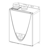
| Model | T-H2-DV |
| Category | Water Heater |
| Type | Tankless |
| Fuel Type | Natural Gas |
| Energy Factor | 0.82 |
| Gallons Per Minute (GPM) @ 77°F rise | 9.8 GPM |
| Voltage | 120V |
| Dimensions | 26.5 x 18.5 x 11.5 inches |
| Weight | 50 lbs |
| Venting | Direct Vent |
| Power | 2W |
| Max. Input | 199, 000 BTU/hr |