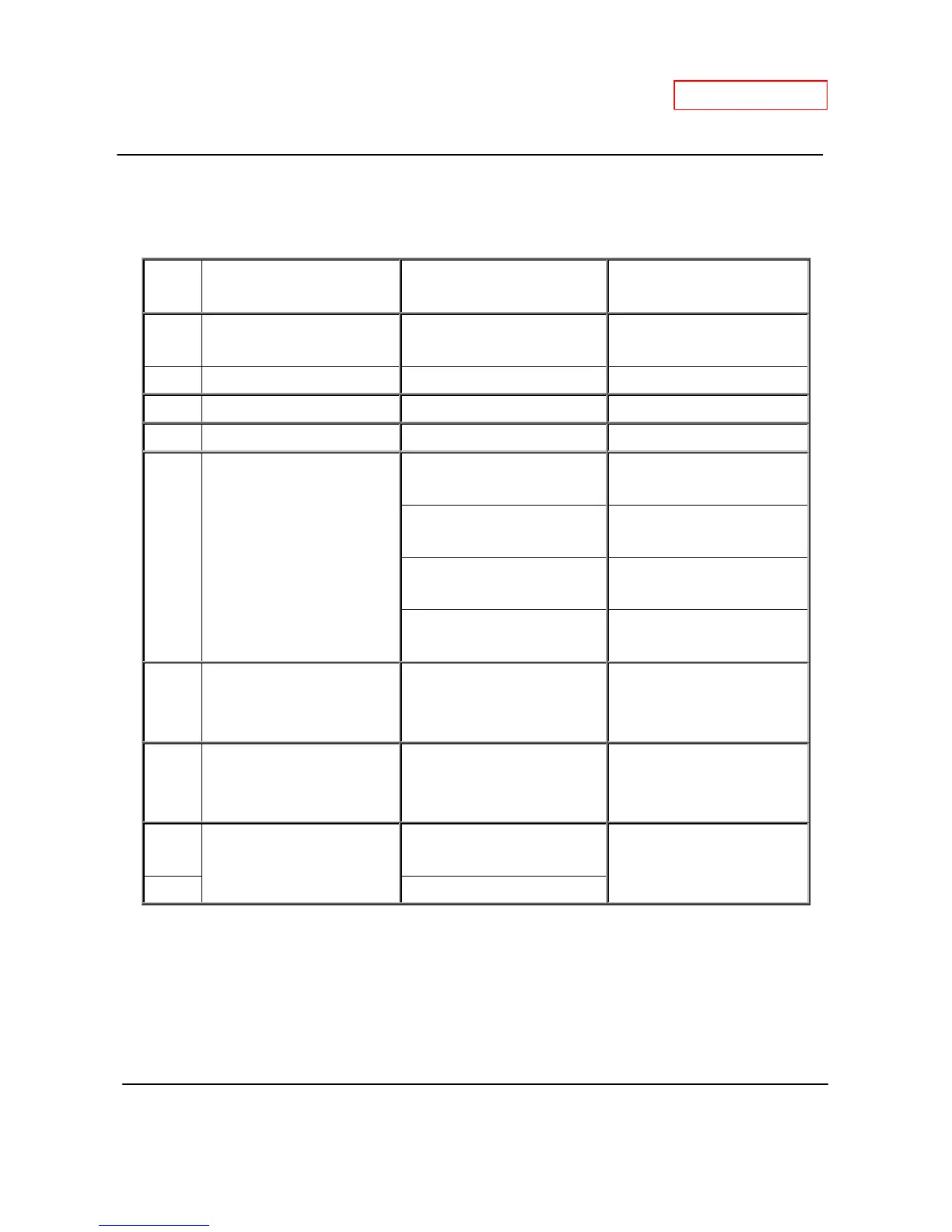
7. Wiring diagram check points for diagnosis
The table below applies to both the T-H2-DV and the T-H2-OS.
Check-
100V Power supply
White – Black (A)
Brown – Brown (A1)
90 to 110 VAC
A2 120V Power supply Black - White 108 to 132 VAC
B1 Heater Black - Black 90 to 110 VAC
B2 Igniter Purple - Purple 90 to 110 VAC
C Gas valves
Light blue - blue at COM (MV)
78 to 100 VDC (during
operation) / 0.9 to 1.3 kΩ
Green - blue at COM (SV1)
78 to 100 VDC (during
operation) / 1.3 to 1.9 kΩ
Orange - blue at COM (SV2)
78 to 100 VDC (during
operation) / 1.3 to 1.9 kΩ
Red - blue at COM (SV3)
78 to 100 VDC (during
operation) / 0.9 to 1.7 kΩ
C1 Hi-limit switch Blue - Blue
Less than 1 VDC
and
less than 1.0 Ω
C2 Overheat cutoff fuse Blue - Blue
Less than 1 VDC
and
less than 1.0 Ω
D1
Easy-link connectors
Red – Red
Blue - Blue
15 VDC
(during Easy-link operation)
D2 White - White
 Loading...