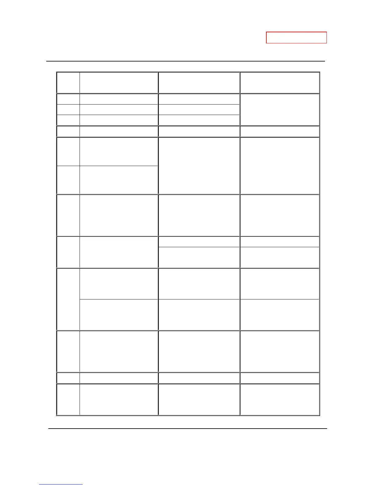
Part and Description Color of wires Normal range
E1 Mixing thermistor Black - Black
See table on p. 14 E2 Output thermistor Black - Black
E3 Inlet thermistor Black - Black
F Remote controller * 11 to 25 VDC
G1 Fan motor
Red – Blue
Yellow – Blue
Orange - Blue
110 to 160 VDC
13 to 17 VDC
2 to 6.5 VDC
G2 Fan motor for exhaust
H1 Gas proportional valve White - red
1 to 15 VDC
(during operation)
and
20 to 40 Ω
H2 Flow sensor
Red - Black 4 to 5.5 VDC
White(+) – Black(GND)
1 to 4 VDC
(1,200pulse / min)
I
Air-fuel ratio flame rod
Yellow - AFR rod
(Between AFR rod and
the computer board)
More than 1 μA
(during operation)
Flame rod
Orange - Flame rod
(Between flame rod and
the computer board)
More than 1 μA
(during operation)
J Water control valve
Blue – Brown
Orange – Brown
Red – Brown
13.0 to 16.0 VDC
ON: 12.5 to 16.0 VDC
OFF: 0 to 1 VDC
1 VDC Less ( 0° position)
K1 Exhaust thermistor White - White See table on p. 15
K2 Hi-limit switch for exhaust White - White
Less than 1 VDC
and
less than 1.0 Ω
 Loading...