bdi
Access
JTAG interface library, BDI2000 (MIPS32) Installation Manual 4
© Copyright 1992-2004 by ABATRON AG V 1.00
2 Installation
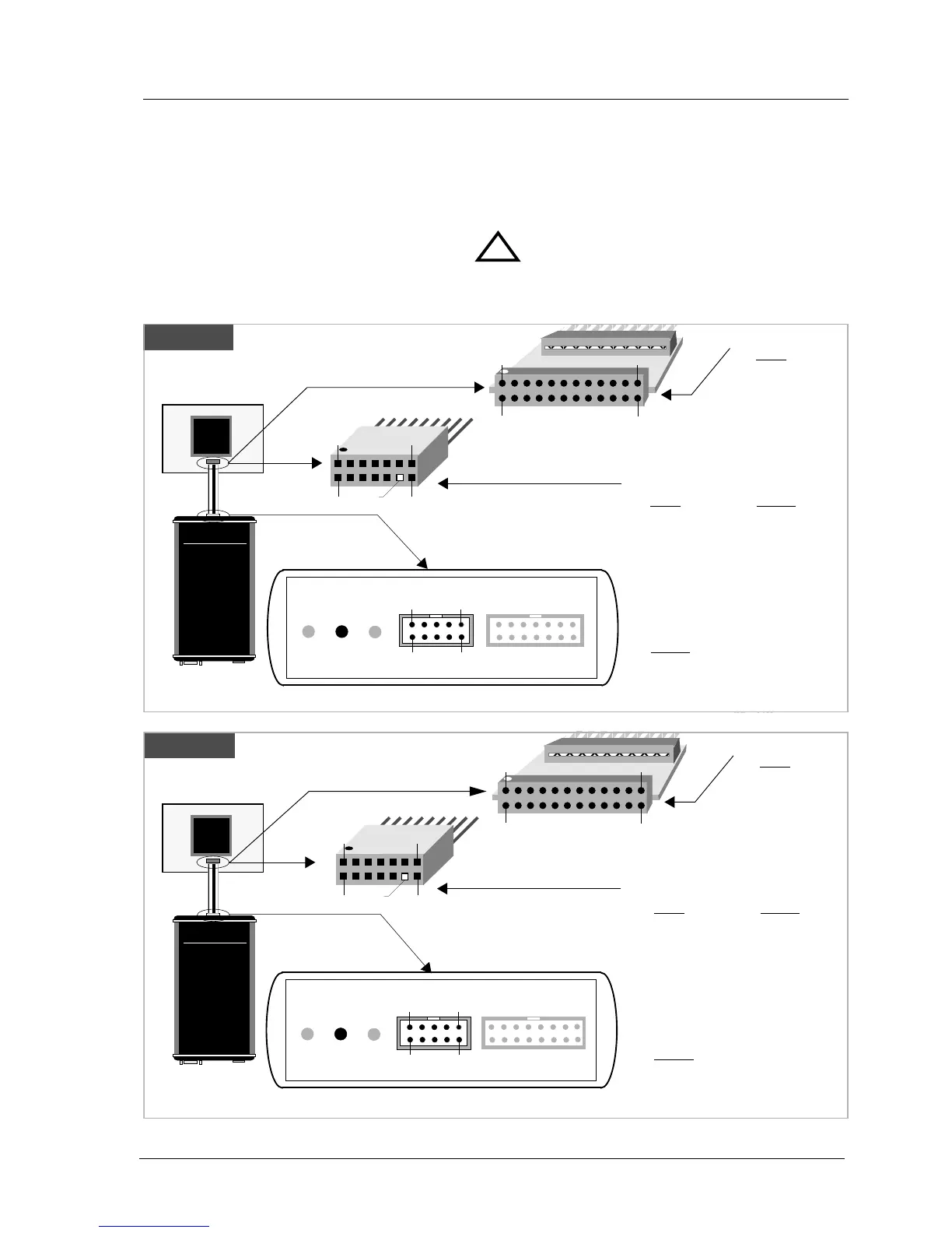
2.1 Connecting the BDI2000 to Target
The cables to the target system are designed for the IDT RC32300 Development Boards (optional
available: Part# 90070) and for EJTAG 2.5 compatible boards (enclosed). In case where the target
system has the same connector layout, the cable (14 pin or 24 pin) can be directly connected.
In order to ensure reliable operation of the BDI (EMC, runtimes, etc.) the target cable length must not
exceed 25 cm (10").
For BDI MAIN / TARGET A connector signals see table on next page.
!
BDI TRGT MODE BDI MAIN BDI OPTION
14 pin EJTAG
BDI2000
AA
AA
bb
bb
aa
aa
tt
tt
rr
rr
oo
oo
nn
nn
AA
AA
GG
GG
SS
SS
ww
ww
ii
ii
ss
ss
ss
ss
MM
MM
aa
aa
dd
dd
ee
ee
Target System
MIPS
9
1
13
14
2
1
10
2
The green LED «TRGT» marked light up when target is powered up
Rev. A
1
24
2
Connector
1 - TRST
2 - GROUND
3 - TDI
4 - GROUND
5 - TDO
6 - GROUND
7 - TMS
8 - GROUND
9 - TCK
10 - GROUND
11 - RESET
12 - GROUND
13 - NC
14 - GROUND
15 - NC
16 - GROUND
17 - NC
18 - GROUND
19 - NC
20 - GROUND
21 - DBGBOOT
22 - GROUND
23 - VIO Target
24 - GROUND