Detailed working procedure
NoteAction
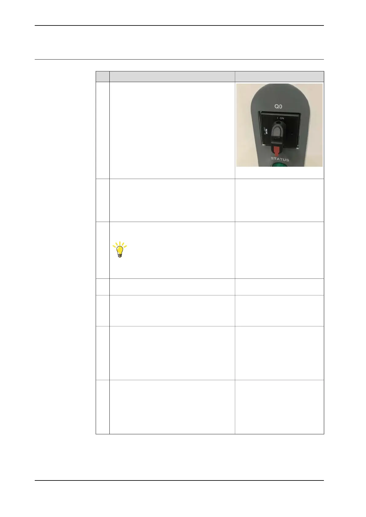
xx2000000445
Make sure that the power inlet switch (Q0) has
been switched on.
1
Use a multimeter and insulating
gloves.
Make sure that the system is supplied with power.
• Measure incoming mains voltage and make
sure the voltage is within the normal range.
• Make sure that the circuit breaker (if used)
is closed.
2
If the incoming power is not ok, the
problem is not in the robot control-
ler. Troubleshoot the incoming
power.
Check that the connector (X0) is properly connec-
ted.
Tip
For more details, see Circuit diagram - OmniCore
C90XT.
3
Check that the AC input cable is properly connec-
ted.
4
Use a multimeter and insulating
gloves.
Check the output voltage of (Q0).
• Make sure that (Q0) is closed.
5
Replace if damaged, see Replacing
the power inlet on page 309.
• If the controller is for CRB
15000, troubleshoot the
power unit. See
Troubleshooting the power
unit on page 388.
• If the controller is not for
CRB 15000, proceed with
next step.
Confirm that the controller is for CRB 15000 or
not.
6
• If abnormal, troubleshoot
the power unit. See
Troubleshooting the power
unit on page 388.
• If normal, troubleshoot the
power supply unit.
SeeTroubleshooting the
power supply on page 407.
Check connector T2.X1.7
366 Product manual - OmniCore C90XT
3HAC073706-001 Revision: E
© Copyright 2020-2021 ABB. All rights reserved.
7 Troubleshooting
7.2.1 No LEDs are lit on the controller
Continued