Operation Manual / A150-M56/66/57/67 - A155-M..
10 Dismantling and fitting with removed air inlet and gas outlet / 10.4
Removing the cartridge group with compressor and turbine casing
© Copyright 2021 ABB. All rights reserved. HZTL4032_EN Rev.Q January 2021
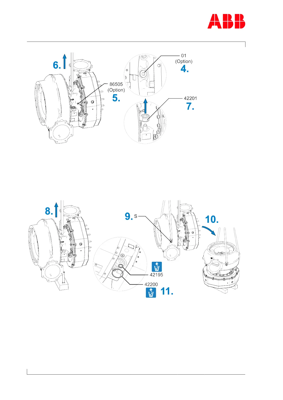
Fig.55: Removing the cartridge group with compressor and turbine casing
4. If present: Loosen and remove the compressor wheel cooling connection. Close the com-
pressor wheel cooling opening with a screw plug(01).
5. If present: Disconnect the plug to the speed sensor (86505) and secure the rolled-up
cable on the turbocharger. This protects the plug from being crushed.
6. Attach lifting gear to the cartridge group and secure to a crane.
7. Loosen clamping nut (see Loosening the clamping nut →31).
Fig.56: Set down the cartridge group with the compressor and turbine casing
8. Lift the cartridge group with the compressor and turbine casing.
9. Fit two swivel lifting eyes (S) and secure to a second set of lifting gear.
10. Turn the compressor and turbine casing and set down on suitable supports.
11. Remove lifting gear from cartridge group. Leave second lifting gear attached to com-
pressor casing for safety.
12. Remove and dispose of the O-rings (42195, 42200).
Page 104 / 194