Fault
P
I
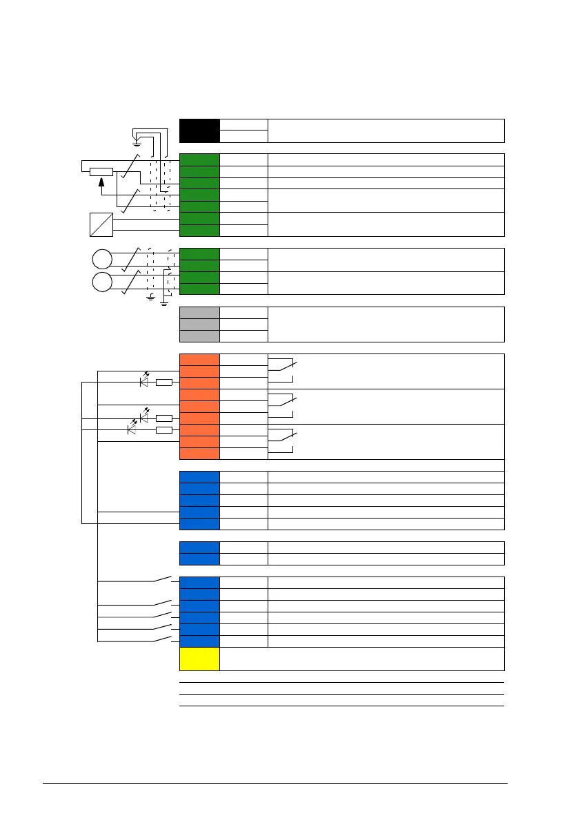
XPOW External power input
1 +24VI
24 V DC, 2 A
2 GND
XAI Reference voltage and analog inputs
1 +VREF 10 V DC, R
L
1…10 kohm
2 -VREF -10 V DC, R
L
1…10 kohm
3 AGND Ground
4 AI1+ Speed reference
0(2)…10 V, R
in
> 200 kohm
5 AI1-
6 AI2+ Process feedback*
0(4)…20 mA, R
in
= 100 ohm
7 AI2-
XAO Analog outputs
1 AO1 Motor speed rpm
0…20 mA, R
L
< 500 ohm
2 AGND
3 AO2 Motor current
0…20 mA, R
L
< 500 ohm
4 AGND
XD2D Drive-to-drive link
1 B
Master/follower, drive-to-drive or embedded fieldbus
interface connection
2 A
3 BGND
XRO1, XRO2, XRO3 Relay outputs
1 NC
Ready run
250 V AC / 30 V DC
2 A
2 COM
3 NO
1 NC
Running
250 V AC / 30 V DC
2 A
2 COM
3 NO
1 NC
Fault (-1)
250 V AC / 30 V DC
2 A
2 COM
3 NO
XD24 Digital interlock
1 DIIL Digital interlock. By default, not in use.
2 +24VD +24 V DC 200 mA
3 DICOM Digital input ground
4 +24VD +24 V DC 200 mA
5 DIOGND Digital input/output ground
XDIO Digital input/outputs
1 DIO1 Output: Ready run
2 DIO2 Output: Running
XDI Digital inputs
1 DI1 Stop (0) / Start (1) – Speed control
2 DI2 By default, not in use.
3 DI3 Speed control (0) / Process control (1)
4 DI4 Constant speed 1 (1 = On)
5 DI5 Run enable (1 = On)
6 DI6 Stop (0) / Start (1) – Process control
XSTO
Safe torque off circuits must be closed for the drive to start. See
Hardware manual of drive.
X12 Safety options connection
X13 Control panel connection
X205 Memory unit connection
*For sensor connection examples, see page 139.

 Loading...


