English
Français
4
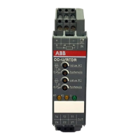
I Front view with operating controls
햲 6 lateral DIP switches, SW 1.1 ... 1.6, for input and
output configuration
With the 6 lateral switches it is possible to configure
5 temperature ranges, as well as the operating mode of
the output relay as shown in table 1.
햳 Potentiometer for the adjustment of the threshold
value R1
햴 Potentiometer for the adjustment of the threshold
value R2
햵 Potentiometer for the adjustment of the hysteresis R1
Adjustment range: 5-50 %
햶 Potentiometer for the adjustment of the hysteresis R2
Adjustment range: 5-50 %
햷 U: green LED - Indication of supply voltage
햸 R1: yellow LED - Output relay 1 energized
햹 R2: yellow LED - Output relay 2 energized
II Electrical connection
For the rated supply voltage and the circuit
diagram, see label at the side of the unit.
K - M Supply voltage
Input signal:
G(+) - H(-) - J(-) PT100 resistance
Output relays:
D - E - F (11-12/14) Relay R1 (c/o contact)
Overtemperature
A - B - C (21-22/24) Relay R2 (c/o contact)
Undertemperature
When connecting a two-wire sensor, jumper the terminals
J and H !
I Face avant et dispositifs de
commande
햲 6 micro-interrupteurs latéraux, SW 1.1 ... 1.6, pour la
configuration de l’entrée et de la sortie
Avec ces 6 interrupteurs, il est possible de configurer
5 plages de température, de même que le mode de
fonctionnement du relais de sortie selon le tableau 1.
햳 Potentiomètre pour le réglage de la valeur de seuil R1
햴 Potentiomètre pour le réglage de la valeur de seuil R2
햵 Potentiomètre pour le réglage de l’hystérésis R1
Plage de réglage: 5-50 %
햶 Potentiomètre pour le réglage de l’hystérésis R2
Plage de réglage: 5-50 %
햷 U: LED verte - Indication de la tension
d’alimentation
햸 R1: LED jaune - Relais de sortie 1 excité
햹 R2: LED jaune - Relais de sortie 2 excité
II Raccordement électrique
Pour la tension assignée d’alimentation et pour le
schéma des connexions, voir l’étiquette placée
sur le côté de l’appareil.
K - M Tension d’alimentation
Signal d’entrée:
G(+) - H(-) - J(-) PT100-résistance
Relais de sortie:
D - E - F (11-12/14) Relais R1 (inverseur)
Température escessive
A - B - C (21-22/24) Relais R2 (inverseur)
Température insuffisante
Quand un détecteur bifilaire est raccordé, ponter les bornes
J et H !

 Loading...