EasyManua.ls Logo

ABB CM-UFD.M22 User Manual

ABB CM-UFD.M22
12 pages
Go to English
To Next Page IconTo Next Page
Page #1 background imageLoading...
Page #1 background image
CM-UFD.M22
Warnung! Gefährliche Spannung! Installation nur durch
elektro technische Fachkraft.
Warning! Hazardous voltage! Installation by person with electro-
technical expertise only.
Avertissement! Tension électrique dangereuse! Installation
uniquement par des personnes qualifiées en électrotechnique.
¡Advertencia! ¡Tensión peligrosa! La instalación deberá ser
realizada únicamente por electricistas especializados.
Avvertenza! Tensione pericolosa! Far installare solo da un
elettricista specializzato.
Varning! Farlig spänning! Installation får endast utföras av en
elektriker.
Oсторожно! Опасное напряжение! Монтаж должен
выполняться только специалистом-электриком.
য়ߢƽླ၃ۉუƽৈᆯۉഘጆᄽටᇵҾጎă
(IT) Istruzioni per l’uso ed il montaggio
Relè di protezione di interfaccia serie CM
Relè di protezione di interfaccia in accordo
con la norma CEI 0-21: Connessione di utenti
attivi alle reti di bassa tensione
Nota: Le presenti istruzioni per l’uso ed il montaggio non
contengono tutte le informazioni di dettaglio sull‘intera
gamma di prodotti e non possono trattare tutti i casi
applicativi. Tutte le indicazioni servono esclusivamente a
descrivere il prodotto e non costituiscono alcuna
obbligazione contrattuale. Per ulteriori informazioni
consultare i cataloghi ed i data sheet dei prodotti, o la
nostra homepage www.abb.com, oppure rivolgersi alla
filiale locale di ABB. Ci riserviamo il diritto di effettuare
eventuali modifiche tecniche.
(EN) Operating and installation instructions
Grid feeding monitoring relay, CM range
Interface protection according to CEI 0-21:
Connection to the low voltage grid
Note: These operating and installation instructions cannot
claim to contain all detailed information of all types of this
product range and can even not consider every possible
application of the products. All statements serve exclusively
to describe the product and have not to be understood as
contractually agreed characteristics. Further information
and data is obtainable from the catalogues and data sheets
of this product, from the local ABB sales organisations as
well as on the ABB homepage www.abb.com. Subject to
change without prior notice.
Doc.no. 1SVC 560 510 M0001 C (02/18)
1
2
2CDC 253 002 F0014
3
1
2
2CDC 253 003 F0014
T
a
: -20 ... +60 °C (-4 ... +140 °F)
IP 20
Pollution degree 3
Nota importante:
Lunghezza massima dei cavi agli ingressi di comando: 10 m
Fusibile di protezione per:
- alimentazione ausiliaria: 6 A gL/gG
- ingresso di misura: fusibile sec. la protezione di linea richiesta
(esempio: 3 x 16 A)
Important notice:
The cable length at the control inputs must not exceed 10 m.
Protection fuse for:
- control supply input: 6 A gL/gG
- measuring input: fuse size acc. to the required line protection
(example: 3 x 16 A)
ABB STOTZ-KONTAKT GmbH, Eppelheimer Straße 82, 69123 Heidelberg / Germany; www.abb.com/lowvoltage
Question and Answer IconNeed help?

Do you have a question about the ABB CM-UFD.M22 and is the answer not in the manual?

ABB CM-UFD.M22 Specifications

General IconGeneral
Number of Contacts2
Mounting TypeDIN rail mounting
Terminal TypeScrew Terminals
Protection ClassIP20
TypeCM-UFD.M22
Output2 changeover contacts (CO)
Reset Time<100 ms
Electrical Life100, 000 operations at rated load
Mounting35 mm DIN rail
Operating Temperature-25°C to +55°C
Mechanical Life30 x 10⁶ cycles
Storage Temperature-40 ... +85 °C

Summary

Operating and Installation Instructions

Grid Feeding Monitoring Relay, CM Range

Interface protection according to CEI 0-21: Connection to the low voltage grid.

Important Notice

Maximum cable length at control inputs and protection fuse details.

Front View and Controls

Front View with Operating Controls

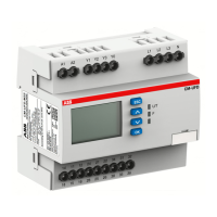
Front view showing display, controls, status LEDs, and operating buttons.

Legend for Front View

Explanation of display, measured values, output relays, control inputs, and LEDs.

Operating Principle

Diagram illustrating remote trip, measurement, and local command functions.

Protective Functions and System Compliance

Designation of Protective Functions according to CEI 0-21

Mapping device parameters to CEI 0-21 standards for over/under voltage/frequency.

Measurement Screen

Display of real-time and 10-min average line-to-neutral voltages.

Menu Structure Overview

Overview of submenus, configuration possibilities, and pre-settings.

Submenu: Nominal Voltage

Configuration of nominal voltage settings and measuring principles.

Configuration and Monitoring Submenus

Submenu: I/O Setup

Settings for relay configurations, startup/restart delays, and feedback loop.

Submenu: Monitoring Functions

Configuration of over/under voltage/frequency thresholds and ROCOF.

Advanced Settings and Diagnostics

Submenu: Autotest

Procedure to start verification of protective functions.

Submenu: General Settings

Configuration for local command, language, display, password, and loading settings.

Submenu: Error Memory

Access to error list, recording, reset, and operating counters.

Related product manuals