4.4 Jumper Selections
4.4.1 Integral Converter
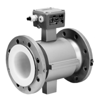
For the Model 10DX3311E integral magmeter, zero return and functions associated with the
50XM1000 signal converter are established by the movable jumpers on terminal-strip J1 located in
the lower left corner of the 686B762U02 Primary Board assembly. The following table and diagram
correlates the zero return and functions with the jumper connections:
The full view of the 686B762U02 Primary Board Assembly is shown in Figure 4-3. Table 4-1 shows
selectable functions and their respective jumper settings.
TABLE 4-1. 686B762U02 PCB JUMPER FUNCTIONS
JUMPER NO. POSITION FUNCTION
J1 1-2 *
3-4 *
5-6 *
7-8
9-10
Zero Return
10 KHz Signal
Reverse Pulse Signal
GND for 10 KHz, Zero Return
COMMON for Reverse Pulse
P4 1-2 ** Integral Converter
P5, P6 2-3 ** CD-1, XM1000 Mode
J2 1-2
1-6
2-5
3-4
** IEX = 85 to 141 mA
IEX = 125 to 230 mA
IEX = 210 to 350 mA
IEX = 337 to 560 mA
P2 - Not to be Jumpered
* Mutually exclusive, only one function at a time may be selected
** Indicates factory default positions
Series 10DX3000 Magnetic Flowmeter Instruction Manual
4-7
 Loading...

