Operation Manual / TPS44-F.. - TPS61-F..
Disassembly and assembly 8
Disassembling and assembling
turbocharger
8.3 Page 106
© Copyright 2016 ABB. All rights reserved.
August 2017HZTL2412_ENRevision F
NOTICE
If two turbochargers are mounted on an engine, one with a left-hand
and one with a right-hand oil inlet, a pin can be fitted in the bracket as a
precaution against incorrect positioning. This pin (B) locates in a corre-
spponing groove in the foot of the bearing casing.
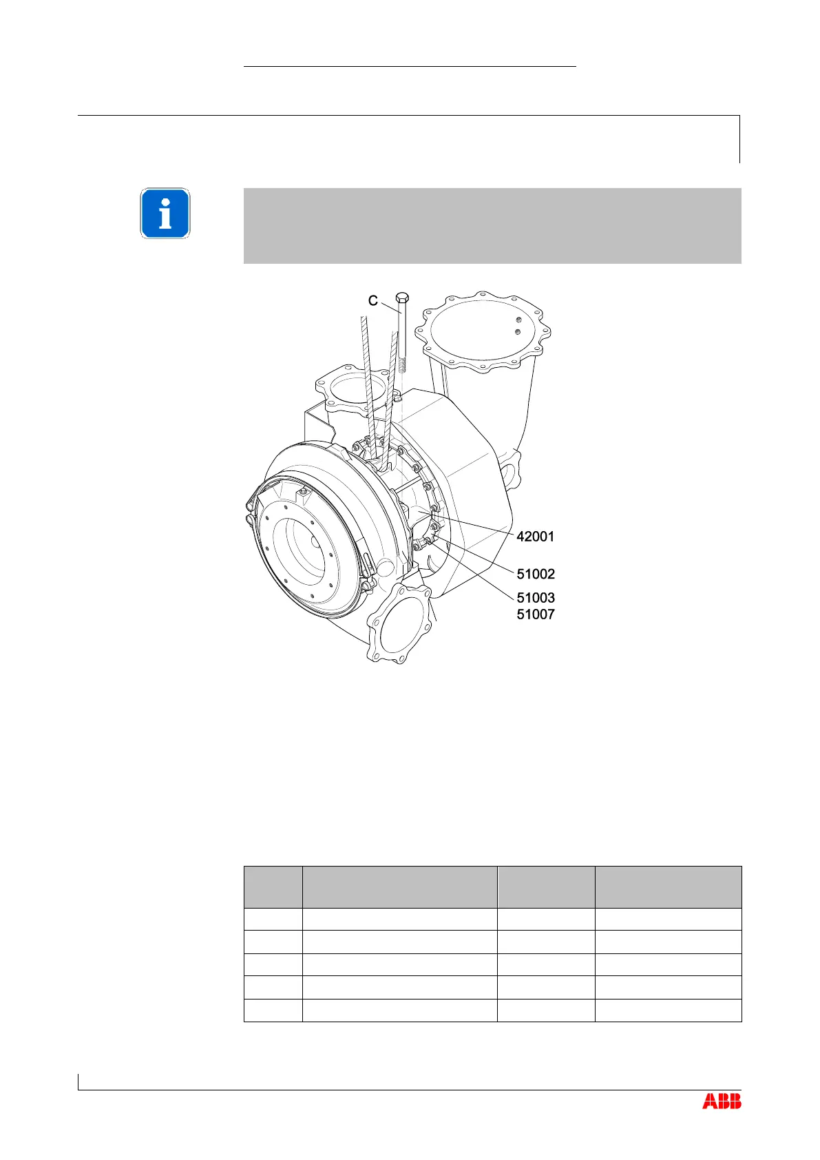
τ Fasten the cartridge group using fastening strips (51002), Verbus
Ripp® washers (51003) and nuts (51007) (also see the chapter enti-
tled Table of tightening torques).
τ Fasten the bearing casing (42001) using the fixing screws (C).
τ Tighten the fixing screws (C) to the torques listed in the following table.
**) For the assembly of the turbocharger on the engine support, the
threads of the screws and screw heads must be lightly oiled (assumed
coefficient of friction µ = 0.12 for the tightening torque).
Product Hole in the bearing casing
[mm]
Fixing screws
C [mm]
Tightening torques
[Nm] **)
TPS44 Ø 17 M16 230
TPS48 Ø 17 M16 230
TPS52 Ø 21 M20 455
TPS57 Ø 21 M20 455
TPS61 Ø 25 M24 780
 Loading...