Operation Manual / TPS44-F.. - TPS61-F..
Disassembly and assembly 8
Disassembling and assembling
turbocharger
8.3 Page 97
© Copyright 2016 ABB. All rights reserved.
August 2017HZTL2412_ENRevision F
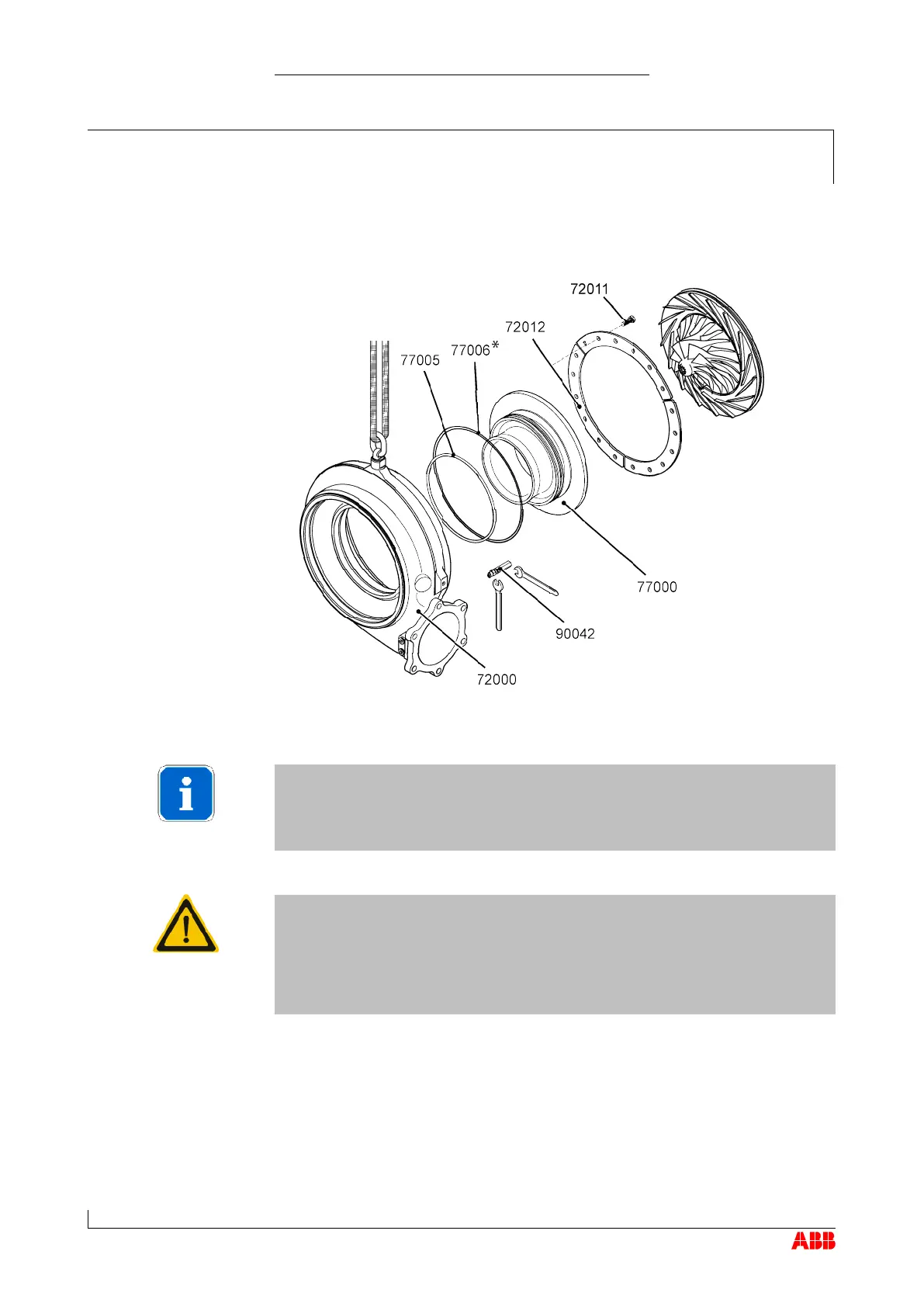
τ Slightly loosen the screws (72011) and turn the compressor casing
(72000) until the swivel lifting eye can be fastened to the lifting gear.
(77006* only provided with the wall insert with acceleration aid.)
NOTICE
If the compressor casing cannot be removed easily, it can be pressed
off using the press-off tool (90042) against the turbine casing. To do
this, the two cover plates (1, 2) must be removed from the hard insula-
tion on the turbine casing.
CAUTION
Axial force
The press-off tool can generate a high axial force and, if it is not used
properly (too much pressure on one side), it can damage the rotor.
τ It should thus be used alternately on both sides while avoiding ex-
cessive pressure on either side.
τ Loosen the screws (72011) and remove them together with the fas-
tening strips (72012).
τ Move the compressor casing (72000) with the wall insert (77000) care-
fully away, doing so horizontally.
τ Tap the wall insert (77000) out of the compressor casing using a nylon
hammer and remove the O-ring seal (77005).
 Loading...