Operation Manual / TPL67-C.. - TPL71-C..
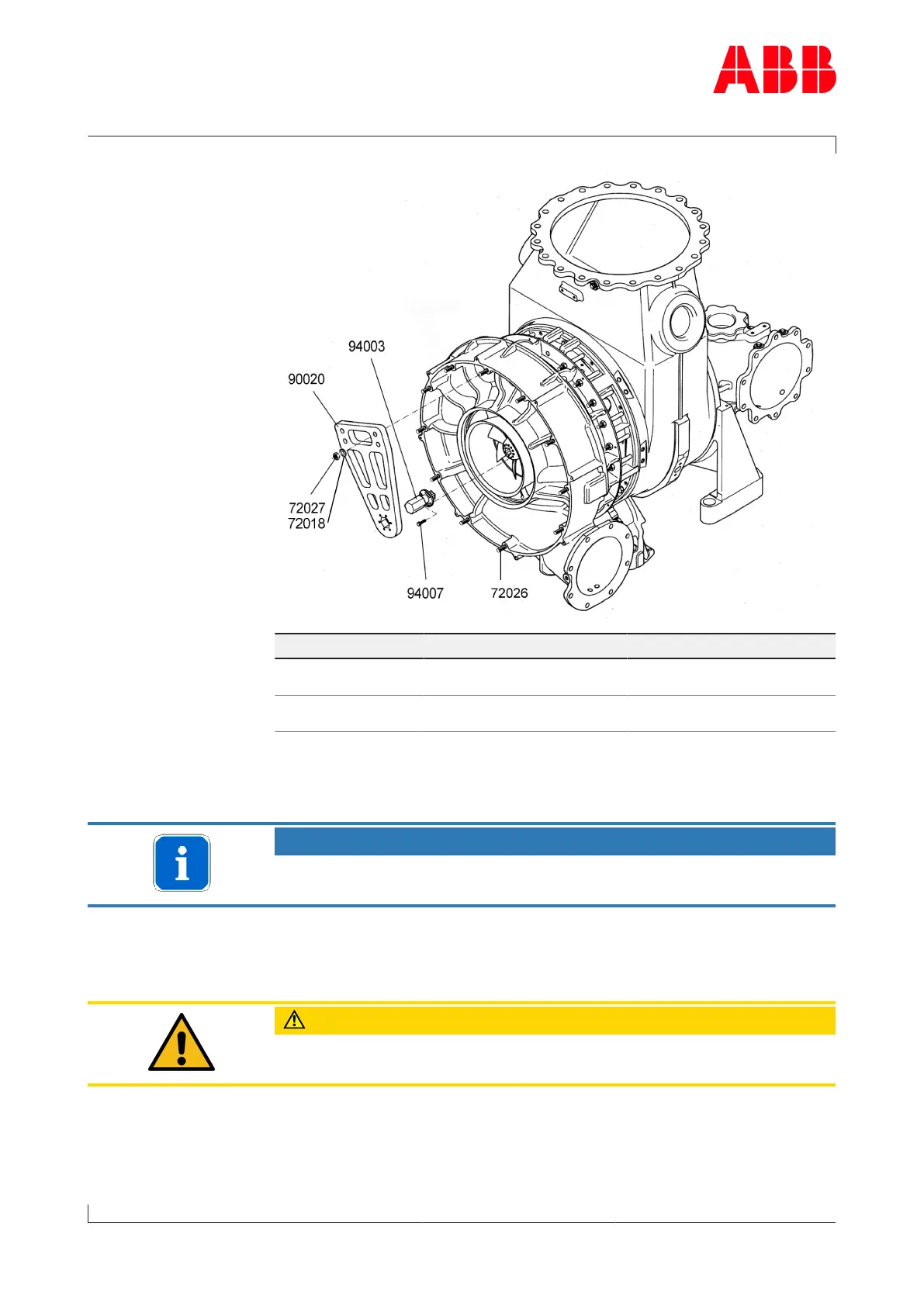
9 Taking out of operation at short notice / 9.2 Locking the rotor
© Copyright 2020 . All rights reserved. HZTL2488_EN Rev.G March 2020
Table of tightening
torques
Part no. TPL67-C TPL71-C
72027 M14
75Nm
M16
105Nm
94007 M8
25Nm
M8
25Nm
u Remove silencer or air suction branch.
NOTICE
Carry out the work as described in the chapter Disassembly and As-
sembly.
u Insert locking flange (94003) into compressor wheel.
u Put screws (94007) into unoccupied threaded holes in compressor
wheel and tighten to values shown in Table of tightening torques.
CAUTION
Do not remove any balancing screws from compressor wheel. Use only
unoccupied threaded holes to fit lifting spigot.
u Position assembly / disassembly device (90020) over studs (72026)
and locking flange (94003).
u Turn compressor wheel so that locking flange hexagon aligns with
hexagon in assembly / disassembly device (90020).
Page 108 / 125