EasyManua.ls Logo

ABB Infinity S J5964803 L209 - User Manual

ABB Infinity S J5964803 L209
7 pages
Print Icon
To Next Page IconTo Next Page
Loading...
QUICK START GUIDE
Page 1
© 2021 ABB. All rights reserved.
Infinity S 19" Universal Power Shelf
Models: J5964803 L209-L216
Sockets - 5/16”, 7/16”, etc.
Screwdrivers - Philips #1 and #2, Flat small
Inter-Shelf Bracket
Step 2 - Connect Chassis Ground
Lug Landings: #10 double-hole on 5/8-inch center
(lugs not provided)
Some applications may rely on frame mounting
screws for shelf ground omitting the chassis ground
cable.
Minimum 10 AWG wire is recommended.
Torque 10-32 screws to 30 in-lb (3.4Nm) - 5/16”
socket.
Knockout
2 Adjacent Shelves
Mounting Ears
Chassis Ground
AC Wiring Box
Tools required
Wire cutters and strippers
Cable crimpers
Torque wrench - 0-65 in-lb (0-10Nm)
Step 1 - Mount Shelf
1. Reposition mounting ears as required - 4 screws
each. Torque to 25 in-lb (2.8Nm) - Phillips
screwdriver.
2. Install Inter-Shelf brackets between adjacent
shelves (optional). Torque to 25 in-lb (2.8Nm) - Philli
screwdriver
3. Attach shelf to the frame using a minimum of four
screws (two on each side) - 12-24 (provided). Torque
to 35 in-lb (4Nm) - 5/16” socket.
Universal Power Shelves accept +24V and 48V rectifiers and converters.
Primary shelf (L209, L211, L213, & L215) includes controller slot. Install shelf immediately below distribution, if used.
Expansion shelf (L210, L212, L214, & L216) includes cables and hardware to connect to an adjacent shelf.
No vertical spacing is required. Provide 2 inch minimum clearance at back of shelf for rectifier airflow.
Refer to Infinity S Flex Power System Brochure for details and accessories.
-
Question and Answer IconNeed help?

Do you have a question about the ABB Infinity S J5964803 L209 and is the answer not in the manual?

Overview

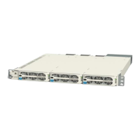
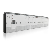
The ABB Infinity S 19" Universal Power Shelf (Models: J594803 L209-L216) is a versatile power solution designed to accommodate both +24V and -48V rectifiers and converters. It serves as a foundational component for power systems, with primary shelves (L209, L211, L213, & L215) featuring a controller slot and expansion shelves (L210, L212, L214, & L216) including necessary cables and hardware for connection to an adjacent shelf. This modular design allows for flexible system expansion without requiring vertical spacing between shelves. A minimum 2-inch clearance at the back of the shelf is recommended to ensure adequate airflow for rectifier cooling.

Installation and Mounting:

Mounting the shelf involves repositioning mounting ears with four screws each, torqued to 25 in-lb (2.8Nm) using a Phillips screwdriver. Optional inter-shelf brackets can be installed between adjacent shelves, also torqued to 25 in-lb (2.8Nm). The shelf is then attached to the frame using a minimum of four 12-24 screws (two on each side), torqued to 35 in-lb (4Nm) with a 5/16" socket.

Grounding:

Chassis ground connection is crucial. The shelf features #10 double-hole lug landings on a 5/8-inch center for this purpose (lugs are not provided). Some applications may allow for the omission of a dedicated chassis ground cable if frame mounting screws provide sufficient grounding. A minimum 10 AWG wire is recommended for grounding, and 10-32 screws should be torqued to 30 in-lb (3.4Nm) using a 5/16" socket.

AC Input Connection:

Connecting the AC input requires adherence to local and national wiring rules, and it is critical to turn OFF and lock-out tag-out the AC source before making any connections. The shelf supports various AC input configurations depending on the model:

  • AC3 (IEC320 C20 Receptacles - 1-phase): For models 211, 212, AC receptacles are on the rear. Connect 120V~/200-240V~, 50-60Hz AC cords with C19 receptacles to each shelf AC connector. This configuration supports 1 rectifier per feed with a maximum 10 AWG.
  • AC5 (Terminal Block - 1-phase): For models 215, 216, the AC terminal block is in the rear AC box. Connect 120V~/200-240V~, 50-60Hz AC to the detachable input terminal block. This configuration supports 1 rectifier per feed with a maximum 6 AWG.
  • AC6 (Terminal Block - 3-phase delta): For models 213, 214, the AC terminal block is in the rear AC box. Connect 120V~/200-240V~/277V~, 50-60Hz AC to the detachable input terminal block. This configuration supports 3 rectifiers per feed with a maximum 6 AWG.
  • AC7 (Terminal Block - 3-phase wye): For models 209, 210, the AC terminal block is in the rear AC box. Connect 120V~/200-240V~/277V~, 50-60Hz AC to the detachable input terminal block. This configuration supports 3 rectifiers per feed with a maximum 6 AWG.

For terminal block connections, wires should be stripped to 10 mm for 1-phase (torqued to 7 in-lb / 0.75 Nm) and 12 mm for 3-phase (torqued to 16 in-lb / 1.75 Nm). After tightening, pull on the wires to verify a secure connection. Knockouts are provided for 3/4" conduit or cord grip. External Surge Protective Devices (SPDs) are required on all AC inputs.

DC Output Connection:

DC output connections are located on the rear under covers.

  • Single voltage systems require either +24V OR -48V connections.
  • Dual voltage systems require both +24V AND -48V connections.
  • Bus Connection (to adjacent shelf): Inter-shelf buses joining +24V, -48V, and RETURN outputs of adjacent shelves should be installed and torqued to 65 in-lb (7.3 Nm).
  • Cable Connection (to stand-alone shelf): Lug landings are 2 x 1/4" on 5/8" center, with a maximum 0.7" (18mm) tongue width. Connect cables with suitable lugs to +24V, -48V, and RETURN, torquing to 65 in-lb (7.3 Nm).
  • Important Note: RETURN must be externally connected to DC Reference (CO) ground. External DC protectors must be installed in the non-grounded (non-RETURN) side of the DC path. Verify battery voltage and polarity with a voltmeter before proceeding.

Controller and Shelf Configuration:

  • Set Controller Jumpers (Primary Shelf Only): Configure the LAN Port and Relay settings as per the Galaxy Pulsar Edge Controller Quick Start Guide.
  • Install Controller (Primary Shelf Only): Install the controller into the shelf controller slot following the Galaxy Pulsar Edge Controller Quick Start Guide.
  • Set Shelf Switches: Switches are located on the rear.
    • SW1: Sets the Rectifier output voltage for the shelf (48V or 24V).
    • SW2: Sets the Shelf Number (1 for the 1st shelf, 2 for the 2nd shelf, etc.). An ID conflict alarm will occur if two shelves are set to the same number.

Signal and Communications Cables:

Connectors are on the rear.

  • J1 (Alarm Inputs and Outputs): For office alarms and signals. Refer to "Information: Alarm Connections" for details.
  • J3-4 (Shelf-to-Shelf communication): Connect adjacent shelves and optionally connect a 1-Wire Battery Temp and Voltage Monitor.
  • J5 (LAN Port): Connect to the Ethernet network.
  • J7 (Distribution Panel signals): Connect to the Distribution Panel if present.

1-Wire Battery Temp and Voltage Monitor (Optional):

Install this monitor per the Galaxy Pulsar Edge Controller Quick Start Guide by connecting it to the upper J3/J4 connector on the Rectifier Shelf with the controller.

Rectifier and Converter Installation:

  1. Slide the unit into the slot approximately 3/4 of the way.
  2. Open the faceplate by sliding the latch to the left until it releases and swings outward.
  3. Slide the unit fully into the slot until it engages with the back of the shelf. Swing the faceplate closed to fully seat the unit, verifying it is latched.

Initial Start-Up:

  1. Verify that all AC, DC, and Alarm connections are complete and secure.
  2. Turn on AC input breakers.
  3. If no alarms are present, make necessary adjustments to the default controller settings for the installation.

Controller Configuration:

Configure the controller per the Galaxy Pulsar Edge Controller Quick Start Guide, verifying and editing basic configuration parameters according to site engineering instructions.

Rectifier and Converter Options (Technical Specifications):

The system supports various rectifier and converter models with specific input/output characteristics and recommended AC breakers.

Rectifiers:

  • NE075AC48ATEZ (-48V blue):
    • Input: ac 277 Vac, Output: 48Vdc, 75A. Recommended AC Breaker: 25A (1-Phase AC3), 25A (3-Phase AC6-delta/AC7-wye).
    • Input: ac 208-240 Vac, Output: 48Vdc, 75A. Recommended AC Breaker: 30A (1-Phase AC5), 50A (3-Phase AC6-delta), 30A (3-Phase AC7-wye).
    • Input: ac 110 Vac, Output: 48Vdc, 25A. Recommended AC Breaker: 20A (1-Phase AC3/AC5).
  • NE050AC48ATEZ / NE50ECO48ATEZ (-48V blue):
    • Input: ac 208-240 Vac, Output: 48Vdc, 50A. Recommended AC Breaker: 20A (1-Phase AC3/AC5), 40A (3-Phase AC6-delta), 20A (3-Phase AC7-wye).
    • Input: ac 110 Vac, Output: 48Vdc, 22A. Recommended AC Breaker: 20A (1-Phase AC3/AC5).
  • NE0100AC24ATEZ / NE100ECO24ATEZ (+24V Orange):
    • Input: ac 208-240 Vac, Output: 24Vdc, 100A. Recommended AC Breaker: 20A (1-Phase AC3/AC5), 40A (3-Phase AC6-delta), 20A (3-Phase AC7-wye).
    • Input: ac 110 Vac, Output: 24Vdc, 44A. Recommended AC Breaker: 20A (1-Phase AC3/AC5).

Converters:

  • NE030DC48A (-48V blue): Input: 24Vdc, 81A max. Output: 48Vdc, 75A.
  • NE040DC48A (-48V blue): Input: 24Vdc, 108A max. Output: 48Vdc, 50A.
  • NE075DC24A (+24V Orange): Input: 48Vdc, 54A max. Output: 24Vdc, 100A.
    • Note: Maximum current at full load and end of discharge voltage (21Vdc or 42Vdc).

IEC Style AC Cords (12 AWG):

A variety of AC cords are available with different plugs and lengths:

  • No plug: 8 ft
  • 5-15P: 8 ft
  • 5-20P: 8 ft
  • 6-15P: 8 ft
  • 6-20P: 8 ft
  • L5-15P: 15 ft
  • L5-20P: 15 ft
  • L6-20P: 15 ft

Alarm Connections:

Alarm connections are on the rear of the shelf. Alarm descriptions can be changed via LAN port (Web pages) or Craft port (EasyView2). The J1 alarm input/output connector has 16 pins with various signals:

  1. Black: User Configurable Alarm Input (Default: Door Open)
  2. White: User Configurable Alarm Input (Default: Aux Major)
  3. Red/Black: PTC3 Protected VBUS-/ABS (Default: Alarm Battery Supply (ABS))
  4. Orange: Power Major Relay Return (Default: PMJ Return)
  5. Orange/Black: Power Minor Relay Return (Default: PMN Return)
  6. Red/White: Relay 1 Return (Default: BD/VLV Return)
  7. White/Black: Relay 2 (Default: AC Fail (ACF))
  8. Blue/Red: Relay 3 and Relay 4 Return (Default: FAJ and Relay 4 Return)
  9. Red: User Configurable Alarm Input (Default: SPD Fail)
  10. Green: User Configurable Alarm Input (Default: AC Fail)
  11. Blue: Relay 4 (Default: Relay 4)
  12. Green/Black: Power Major Relay (Default: PMJ)
  13. Blue/Black: Power Minor Relay (Default: PMN)
  14. Green/White: Relay 1 (Default: BD/VLV)
  15. White/Red: Relay 2 Return (Default: ACF Return)
  16. Orange/Red: Relay 3 (Default: Fuse Alarm Major (FAJ))
    • Relays 1-4 are user configurable.
    • Customer specific factory defaults are detailed in the Quick Start Guide Supplement.
    • Positive Temperature Coefficient resistor protected battery voltage provides up to 0.5A for external alarm circuits.

Alarm Cables (Reference Only):

Various alarm cable lengths are available: 5 ft, 15 ft, 50 ft, and 150 ft.

Specifications and Application:

  • Specifications and Ordering Information: Detailed in the Reference Documents.
  • External Surge Protective Devices (SPDs): Required on all AC inputs.
  • Equipment Safety: Approved in IEC 60664-1 Installation Category II environments.
  • Equipment and subassembly ports:
    • Suitable for connection to intra-building or unexposed wiring or cabling.
    • Can be connected to shielded intra-building cabling grounded at both ends.
  • Grounding / Bonding Network: Supports Isolated Ground Plane (Isolated Bonding Network) or Integrated Ground Plane (Mesh-Bonding Network, or Common Bonding Network).
  • Installation Environment: Designed for Network Telecommunication Facilities, OSP, or where NEC applies.
  • DC Returns: Supports Isolated DC return (DC-I) or Common DC return (DC-C).

Reference Documents:

  • 850035894 Galaxy Pulsar Edge Quick Start Guide
  • CC848815341 Pulsar Edge Controller Family Product Manual
  • Infinity S Flex Power System Brochure

These documents are available at abbpowerconversion.com.

ABB Infinity S J5964803 L209 Specifications

General IconGeneral
BrandABB
ModelInfinity S J5964803 L209
CategoryPower Supply
LanguageEnglish

Related product manuals