76
1MRS750915-MUM
Machine Terminal
Technical Reference Manual, General
REM 54_
5.1.14. Display panel (HMI)
The machine terminal is provided with either a fixed display or an external display
module. The external display module requires a separate voltage supply from a
common source with the main unit (refer to section “Auxiliary voltage” on page 39).
For more information about the rated input voltages, refer to Table 5.2.1-2 on
page 81. A special cable (1MRS120511.001) delivered with the machine terminal is
needed for communication between the terminal and the external display panel.
• graphical LCD display, with the resolution 128 x 160 pixels, consisting of 19
rows divided into two windows
• main window (17 rows) providing detailed information on MIMIC, objects,
events, measurements, control alarms and parameters of the terminal
• assisting window (2 rows) for terminal-dependent protection indications and
alarms, and for general help messages
• three push-buttons for object control
• eight freely programmable alarm LEDs with different colours and modes
according to the configuration (off, green, yellow, red, steady, blinking)
• LED indicator for control test and interlocking
• three protection LED indicators
• HMI push-button section with four arrow buttons and buttons for clear [C] and
enter [E]
• optically isolated serial communication port
• backlight and contrast control
• freely programmable button [F]
• button for remote/local control (Control position button [R\L])
A060270
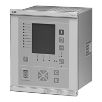
Fig. 5.1.14.-1 Front view of the REM 54_ machine terminal
The HMI has two main levels, the user level and the technical level. The user level
is for everyday measurements and monitoring whereas the technical level is
intended for advanced machine terminal programming.
Programmable LEDs
Object control buttons:
Close
Open
Select
Control position button
Optical PC
connector
Freely programmable
button
Control test &
Interlocking LED
Protection LED indicators:
Left: Ready, IRF, Test mode
Middle: Start, Block
Right: Trip, CBFP
Graphical
LCD display
Main window Assisting window
Enter/Return Clear/CancelNavigation
buttons
REF 541
Uaux = 80...265 Vdc/ac
fn = 50 Hz
In = 1/5 A (I)
1MRS xxxxxx
98150
9509
Ion = 1/5 A (Io)
Un = 100/110 V (U)
Uon = 100/110 V (Uo)
0.0kV
G
CB
DC
0kW
0kVAr
0A
cos(f)0.00

 Loading...