____________________________________________________________________________________________________________
V2 S500 Hardware 1-3 System Data S500 / Issued: 01.2007
S500 System data
The same system data as for the system AC500 apply to the system S500-FBP. Only additional details
are therefore documented here.
Assortment
Parts of the S500-FBP system are
• the FBP Interface Module DC505-FBP
• digital I/O modules
• analog I/O modules
• Terminal Units for the FBP Interface Module and the I/O modules
• accessories
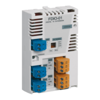
The FBP Interface Module DC505-FBP serves for the data interchange between a fieldbus and the I/O
modules attached to the FBP Interface Module. The FBP interface module itself also has some digital
inputs and outputs. The fieldbus type is defined by the choice of the FieldBusPlug (see documentation
FieldBusPlug / FBP).
Subjects (overview)
Use of the S500 I/O modules ..................................................................................................................... 1-4
Diagnosis LEDs .......................................................................................................................................... 1-5
Mounting and disassembling the Terminal Units and the I/O modules ................................................... 1-13
Mechanical dimensions S500 ................................................................................................................... 1-17
Switch-gear cabinet assembly .................................................................................................................1-19
Connection system .................................................................................................................................. 1-20
Mechanical encoding ............................................................................................................................... 1-24
General wiring recommendations ............................................................................................................ 1-26
Behaviour of the system in case of power supply interruptions and power recovery .............................. 1-26
Block diagrams, earthing concept ............................................................................................................ 1-27