4
PAINOS
PAINOS
B l o c k d i a g r a m
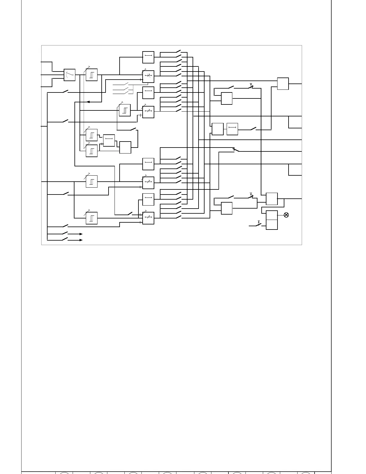
Fig. 1. Block diagram for overcurrent and earth-fault module SPCJ 4D24
IL1, IL2, IL3 Measured phase currents
I
o
Measured neutral current
BS1 External blocking or resetting signal
SGF Programming switchgroup SGF on the front panel
SGB Programming switchgroup SGB on the front panel
SGR1...3 Programming switchgroups SGR on the front panel
TS1 Starting signal1 or auxiliary tripping signal depending on programming
of switchgroup SGR3
SS1 Start signal for stages selected with switchgroup SGR1
SS2 Trip signal 1 for stages selected with switchgroup SGR2
SS3 Trip signal 2 for stages selected with switchgroup SGR2
TS2 Tripping signal from stages selected with switchgroup SGR1
AR1, AR2, AR3 Starting signals to external autoreclose unit
TRIP Red indicator for tripping
Note! All input and output signals of the module are not necessarily wired to the terminals of every relay
assembly using this module. The signals wired to the terminals are shown in the diagram illustrating the flow
of signals between the plug-in modules of the relay assembly.
IL1
IL2
IL3
50 ms
30 ms
50 ms
50 ms
0.12 x I>
60 ms
&
SGR3 / 1
SGR1 / 1
SGR3 / 2
SGR2 / 1
SGR2 / 2
SGR1 / 2
SGR3 / 3
SGR1 / 3
SGR3 / 4
SGR2 / 3
SGR2 / 4
SGF1 / 5
SGR1 / 4
2 x I»
1.5 x I>
1.25 x I>
SGR3 / 5
SGR1 / 5
SGR3 / 6
SGR2 / 5
SGR2 / 6
SGR1 / 6
SGR3 / 7
SGR1 / 7
SGR3 / 8
SGR2 / 7
SGR2 / 8
SGR1 / 8
I>
I»
t»
t>, k
to>
Io>
to»Io»
SGF1 / 1
SGF1 / 2
SGF1 / 3
SGF1 / 6
Io
BS1
SGB / 1
SGB / 2
SGB / 3
SGB / 4
SGB / 5
SGB / 8
REMOTE SETTINGS
RELAY RESET
1
SGB / 6
RESET+
PROGRAM
1
SGB / 7
RESET+
PROGRAM
1
1
1
SGF1 / 4
SS1
SS2
SPCJ 4D24
TS1
TS2
SS3
RESET
TRIP
0.1…1s
SGF2 / 7
AR2
AR1
AR3
SGF2 / 8
 Loading...


