Do you have a question about the ABB SYN 5201 and is the answer not in the manual?
Manual purpose for SYNCHROTACT 5 device.
Explains warning symbols and notes in text.
Applications of the digital synchronizer.
Contact information for ABB Switzerland Ltd.
Overview of SYNCHROTACT 5 functions and types.
Four function blocks of the automatic paralleling process.
Variables generated from voltage measurements.
Working range of the voltage matcher.
Conditions for paralleling voltage-carrying and no-voltage lines.
Distinction between asynchronous and synchronous sources.
Three test functions for matching SYNCHROTACT 5 to installation.
Test for determining paralleling time and tuning voltages.
Test for voltage adjusting characteristic.
Test for frequency adjusting characteristic.
States and modes of the synchronization process.
Four operating statuses: Blocked, Ready, Operating.
Initialisation, parameter set selection, start/stop.
Use of TEST mode for checking synchronization function.
Monitoring functions: hardware, command circuit, software, external events.
Monitoring of auxiliary voltage and command circuit.
Security against incorrect paralleling and watchdog function.
Monitoring for fulfillment of conditions or implausible config.
Permanently stored parameter values and transient data.
Methods for synchronizing device clock.
Service control vs. operating control methods.
Data transmission via service and operating interfaces.
SynView operated service interface functions.
Interface for transmitting normal operation data.
Parameter adjustment and data reading via IEC 61850.
Explanation of the SYNCHROTACT 5 type code structure.
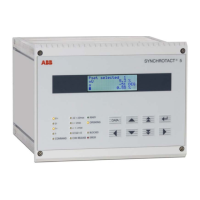
Description of front panel elements including status displays.
Keypad and LCD functions for parameter and value viewing.
Electrical connections and interfaces on the rear panel.
Description of the device's printed circuit board modules.
General overview of parameters, values, and events.
Hierarchical structure of the device's menu system.
Format and display of recorded events.
Table of actual measured values and their menu positions.
Structure and division of parameter sets into functional groups.
Assignment of functions to digital inputs and outputs.
Synchrocheck parameter settings specific to SYN 5202.
Linking parameter sets in dual channel systems.
Detailed parameter settings for various functions.
Procedure for TEST ton function for command generation.
Slip limit settings based on application type.
Settings for zero voltage and release of measuring voltages.
Test function for voltage adjusting characteristic.
Test function for frequency adjusting characteristic.
Blocking time and total paralleling time parameters.
Assignment of functions to digital inputs and outputs.
Synchrocheck parameter settings for channel 2.
Addressing and configuration for Modbus RTU interface.
Configuration using DIP switches for Modbus RTU.
Addressing and configuration for Profibus DP interface.
Configuration using decimal switches for Profibus DP.
Addressing and data transmission for Lon-Bus.
Service key requirement for Lon-Bus configuration.
Data model for IEC 61850 interface.
Logical nodes and their application in IEC 61850.
IP address configuration for IEC 61850 interface.
General recommendations for cable connections and wiring.
Recommendations for connecting cables to terminals.
Measures for long cable runs.
Instructions for connecting measuring voltages.
Operation with single-phase measuring signals.
Using compensation VT for phase angle difference.
Step-by-step sequence for synchronizing process.
Configuring digital inputs and outputs for parameter sets.
Examples of assigning multiple parameter sets to a point.
Example of assigning one parameter set to multiple points.
Using inputs/outputs for signaling or control.
Parameter settings to use the device as a synchrocheck.
Information on service and operating interfaces.
Service interface for commissioning and maintenance.
Operating interface for operational control.
Configuration and data model for IEC 61850 interface.
Methods for time synchronization.
Synchronization using pulses.
Synchronization via serial interface.
Synchronization via IEC 61850.
Function of SYN 5500 auxiliary device.
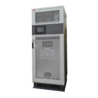
Physical dimensions of the SYNCHROTACT 5 device.
Instructions for physically mounting the device.
Guidelines for earthing and cable shielding.
Environmental considerations for equipment disposal.
Commands for commissioning and maintenance via keypad.
List of commands executable from the keypad.
Description of device display types and their comments.
Using SynView for device control and setup.
Establishing a direct PC connection to the device.
Connecting the device to a PC over a network.
Usage and password settings for SynView software.
Controlling the device via digital inputs.
Initiating and terminating the synchronization process.
Using TEST mode for checking synchronization.
Switching between hardwired and operating interface control.
Routing control commands via the operating interface.
Using built-in panel or SynView for service.
Operating the device via IEC 61850 interface.
Configuring the device via direct PC connection.
Functional operation over IEC 61850 network.
User manual for SYN61850Config tool.
Safety warnings and general instructions for commissioning.
Procedures performed when the machine is not running.
Checking electrical connections against schematics.
Checking SYN 5500 jumper positions.
Actuating control inputs via contacts or DC supply.
Initial power-up procedure and status indications.
Connecting PC and SynView to the device.
Time synchronization procedures using SynView.
Verifying communication interface connectors and settings.
Checking device operation and data transfer.
Initial parameter settings and writing to RAM.
Checking paralleling command and measuring circuits.
Testing phase sequence and tuning voltage measurements.
Adjusting matchers to the plant while the machine is operational.
Adapting voltage and speed matchers using test functions.
Checking voltage and frequency matchers.
Recommendations for recording parameter settings.
Device requires no maintenance; test synchronizing is recommended.
General information on faults and troubleshooting.
Safety warnings and regulations for fault rectification.
Initial steps for troubleshooting device faults.
Table of event codes, descriptions, and remarks.
Advice for difficult cases and interpreting faults.
Procedure for cancelling active error messages.
Troubleshooting communication interface issues.
Verifying PC addressing and configuration.
Checking interface status and connections.
Verifying device status and blocking input.
Troubleshooting IEC 61850 interface blocking and parameter adjustment.
Status indicators for Ethernet link and activity.
Status indicators for Modbus communication.
Status indicators for Profibus communication.
Status indicators for Lon-Bus communication.
Status indicators for IEC 61850 communication.
Issues with time synchronization for IEC 61850 interface.
Technical specifications for device inputs.
Technical specifications for device outputs.
Specifications for service, time sync, and operating interfaces.
Ethernet interface for SynView with bridgeable distance.
RS232 interface for time synchronization.
Pin assignments for Modbus RTU and Profibus DP interfaces.
Measuring ranges and accuracy specifications.
Voltage, frequency, slip, and acceleration ranges.
Accuracy specifications for measurements and operating parameters.
Climatic, mechanical, and interference immunity specifications.
Isolation test and impulse voltage withstand.
Temperature ranges and climatic tests.
Vibration, shock, and earthquake resistance.
EMC test specifications.
CE conformity and product standards.
Protection type, weight, and installation altitude.
Flammability ratings for device components.
Form for recording device settings and commissioning details.
| Brand | ABB |
|---|---|
| Model | SYN 5201 |
| Category | Recording Equipment |
| Language | English |