Operation Manual / TPL67-C.. - TPL71-C..
Taking out of operation at short notice
Page 117
© Copyright 2017 ABB. All rights reserved.
February 2017 HZTL2488_EN Revision D
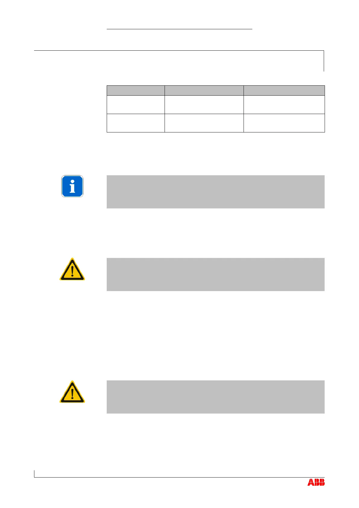
72027 M14
75 Nm
M16
105 Nm
25 Nm
25 Nm
Remove silencer or air suction branch.
Carry out the work as described in the chapter Disassembly and As-
sembly
.
Insert locking flange (94003) into compressor wheel.
Put screws (94007) into unoccupied threaded holes in compressor
wheel and tighten to values shown in
Table of tightening torques
.
Do not remove any balancing screws from compressor wheel. Use only
unoccupied threaded holes to fit lifting spigot.
Position assembly / disassembly device (90020) over studs (72026)
and locking flange (94003).
Turn compressor wheel so that locking flange hexagon aligns with
hexagon in assembly / disassembly device (90020).
Secure assembly / disassembly device (90020) to compressor casing
by screwing nuts (72027) complete with washers (72018) onto studs
(72026) and then tightening to values shown in preceding
Table of
tightening torques
.
Make sure all components are clean and free from grease.
Table of tightening
torques
 Loading...