32
1ZSE 5492-118 en, Rev. 4
TC_00238
TC_00148TC_00147 TC_00170
TC_0238
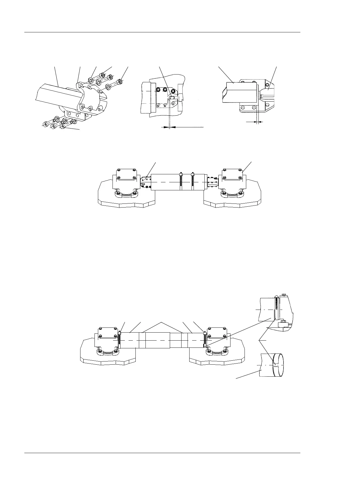
6. Connect the square shaft with the mounted coupling halves to the shaft of the bevel
gear SA21, see Fig. 22. Mount two coupling halves SA11 to the square shaft perpen-
dicular to the coupling in the other end and to the shaft of the bevel gear on the on-load
tap-changer. Tighten light the screws and check that the shaft not can be moved more
than 2 mm in axial direction (axial play). Tighten the two screws A rst and thereafter the
other, see Figs. 19 and 20. If necessary the axial play may be adjusted by moving the
couplings on the shaft end according to Fig.21.
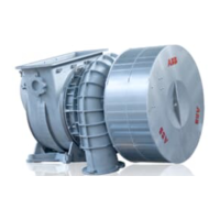
7. Push the two protective tubes on to the bevel gears and clamp them with hose clips,
SA10, see Fig. 23.
NOTE: The slot of the protective tubes SA23 and SA24 shall be facing downwards.
Apply the self-adhesive information plates SA25 around the tubes on about the middle
of the tube length.
5 Final assembly
SA21
Fig. 19. Fig. 21.Fig. 20.
ASA13SA12SA11Square shaft Driving pin
A
SA11
Square shaft
SA11
Max. 3 mm
Max. 6 mm
Slot facing
downwards
SA25SA10 SA24 SA23 SA10
SA23
Fig. 22.
Fig. 23.