13.
Grid support functions AFD (arc fault detection)
10.
Commissioning
10.
Commissioning
9.
User Interface
11.
Response to abnormal conditions
UNO-DM-3.3_3.8_4.6_5.0-TL-PLUS-US-Q-Quick Installation Guide EN-RevA
EFFECTIVE 2019-05-30
© Copyright 2019 ABB. All Rights Reserved.
Specications and illustrations subject to change without notice.
8.
AC Output connection
12.
SN WLAN: SSSSSSSSSS
PN WLAN: PPP.PPPPP.PP
MAC: XX:XX:XX:XX:XX:XX
SN Inverter: SSSSSSSSSS
MAC: XX:XX:XX:XX:XX:XX
PK: KKKK-KKKK-KKKK-KKKK
Remove and apply
on the Quick
installaon guide
→
Contact us
www.abb.com/solarinverters
The inverter is equipped with advanced grid support functionality that is useful to support reactive loads and also assist in reliable operation of the utility grid in
the presence of a large number of distributed energy generation sources. This section provides an overview of the available grid support functions.
The parameters related to the grid support functions that are in this inverter can be modied by:
- Accessing the embedded Web User Interface.
- Accessing to settings under the Service menu requires a time-limited password, which can be obtained by calling ABB solar inverter technical support at 1-877-261-1374.
1. Voltage ride-through
This inverter provides parameters to respond to undervoltage and overvoltage events. The inverter is designed to operate normally within the specied operating range.
If voltage excursions occur, the inverter is designed to continue operating normally or cease to export power for a specied delay. Beyond this programmed delay, the
inverter disconnects from the grid in the event of an abnormal voltage condition.
2. Frequency ride-through
This inverter provides parameters to respond to underfrequency and overfrequency events. If frequency excursions occur, the inverter is designed to continue opera-
ting normally for a specied delay. Beyond this programmed delay, the inverter disconnects from the grid in the event of an abnormal voltage condition.
3. Reactive power control
The inverter provides several modes of operation for reactive power control and are described below:
- Disable: This is the default setting. Under this setting, the inverter exports with a power factor of 1.0.
- Fixed power factor control (Cosɸ set): In this mode, the operator can set the output power factor to a xed value. When enabled, a new value will be set in the
inverter.
- Q Fixed (Q Set): Sets the reactive power to a xed value. When enabled, a new value will be set in the inverter.
- Power factor as function of output power (Watt/Cosφ Settings: Cosφ(P)): In this mode, the inverter reduces the power factor (cos-phi) as a function of the output
power at a given operating point. The 4 points of the default curve, where you can set the % of Pmax values and related cos-phi, can be modied using the internal
Webserver. When enabled, the curve will be set in the inverter.
- Dynamic Volt/VAR control (Volt/VAr Settings: Q(V)): Under this mode, the level of reactive power exported by the inverter is a function of the operating grid voltage,
also known as a Volt/VAR curve. The 4 points of the default curve, where you can set the % of Vnom values and related % of Smax, can be modied using the
internal Webserver. When enabled, the curve will be set in the inverter.
4. Active Power Control
This inverter offers several modes for active power reduction.
- Active Power Curtailment: Sets a new value of active power as % of Pmax. When enabled, a new value will be set in the inverter.
- CEI Average VGrid Derating (only italian grid standard): Sets, after a specic threshold, an active power derating based on the average of Vac on 10 minutes as per
CEI-021 italian grid standard.
- Volt/Watt settings: P(V). Under this mode, the level of active power exported by the inverter is a function of the operating grid voltage, also known as a Volt/Watt cur-
ve. The 4 points of the default curve, where you can set the % of Vnom values and related % of Pmax, can be modied using the internal Webserver. When enabled,
the curve will be set in the inverter.
- Frequency/Watt function (Frequency Control: P(f)): In this mode, the inverter limits the active power as a function of the grid frequency.
5. Ramp control
The inverter is designed to control the rate at which output power is increased, either at startup, or after a temporary low power condition on the PV array (such as fast
shading). The following ramp controls are provided on this inverter.
- Normal ramp: The normal ramp denes the maximum rate at which the inverter can increase the output power under normal operation. The normal ramp control
limits the uctuations in the output power in order to prevent instabilities on the utility grid.
- Soft start: The soft-start ramp denes the maximum rate at which the inverter can increase the output power when the inverter is rst starting up. This startup may
occur on a daily basis or when the inverter restarts after an abnormal grid event has ended.
Refer to the dedicaterd application note in the ABB Solar website for more details about the grid support functions.
To prevent electrocution hazards, open and lock out the external AC disconnect switch before connecting the AC conductors, and any
time the AC wiring box cover is to be removed. Proper PPE is required.
AC output overcurrent protection is not provided with the inverter; it is the responsibility of the end user to provide overcurrent protec-
tion for the AC output circuit. To reduce the risk of re, connect only to a circuit provided with an overcurrent protection in accordance
with the NEC (ANSI/NFPA 70). The inverter must be connected only to a dedicated branch circuit provided with the maximum branch
overcurrent protection device (OCPD) listed in the technical data sheet at the end of this document.
Size conductors per the NEC, Article 310 - use 90°C copper wire only; conductors must be sized according to operating temperature
range and continuous current ratings. The AC grid wiring is connected through the inverter switchbox.
AC output wire must be listed PV wire rated minimum 600V.
- Run an approved raceway between the inverter and external AC disconnect switch.
- Pass the AC wires throught the openings dedicated to the AC conduit.
When complete, seal conduit with water-tight ttings to maintain the NEMA type 4X enclosure rating.
Installer should follow conduit manufacturers’ guidelines and best practices.
- Determine which AC output is applicable for the inverter model being installed.
The AC wiring connections based on the AC grid type are shown in the table
(also found on a label in the wiring box).
208V~
3PH -
240V~
SPLIT-PHASE
GRID STANDARD
TYPE DE RÉSEAU
TERMINAL
BORNE
WIRE
CÂBLE
L2
L1
N
L1
L3 L2
1
L1
2
L2
3
-
CAUTION
Thisisasingle phase inverter. Use thewiringschemes shown on the
table below when adifferent grid standardis used. Refer to the
instruction manual to properly set theinvertergridstandard fromthe
front panel display. Use 90°C copper wire only. Refer to theinstruction
manual forwiringinstructions.
ATTENTION
Ceci est unonduleur monophasé.Utilisez lesschémas de raccordement
ci-dessussileréseau est spécifique.Réferez-vousau manuel
d'installation pour sélectionner via l'afficheur frontal le code pays
adéquat.Utilisez seulement câbles en cuivre90°C.
Consulterle manual d'installation pour lesinstructions de câblage.
AWG# 4 - 8
1
L1
2
L2
3
N
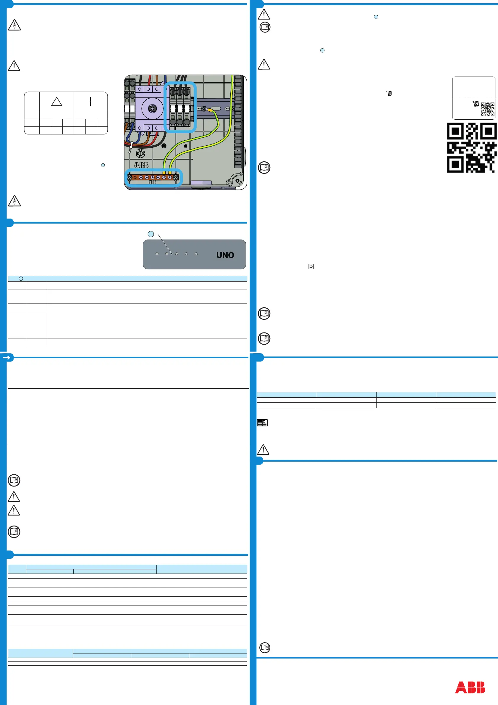
- Connect wiring to the numbered terminals based on selected grid type. AC wiring
terminals are spring pressure type and accommodate a wire size range of 20-6
AWG.
- Connect the protective earth (PE) cable to wiring box busbar
16
. Screws
the cable (max 4 wires 8AWG to 4AWG, copper) with 2.0Nm (1.5ft-lb)
torque.
The default 240V split-phase connection requires the grid Neutral to be connected to the inverter for proper operation. Before connecting
the inverter to the grid, the grid type must be selected during the commissioning phase. If several inverters are installed to a three-phase
AC grid, always distribute the inverters between the phases in order to reduce power imbalance between the phases.
- When all connections are complete, reinstall the front covers and tighten the cover screws with 1.5Nm (13.2 in-lbs) torque.
CAUTION
ATTENTION
REFER TO LOCAL CODE
FOR WIRE SIZE
FAIRE RÉFERENCE À LA
LÉGISLATION LOCALE POUR
LA DIMENSION DU CABLE
-IN1
+IN1
-IN2
+IN2
1
2
3
-RSD
+RSD
Abnormal grid conditions: The inverter is programmed to respond to abnormal grid conditions, as specied in the below table:
Condition
Utility source
Max. time (sec) at 60Hz before cessation of current
Voltage (V) Frequency (Hz)
A <0.50 Vnom
1
(Fixed) Rated (60Hz) Default setting
3
0.16 (Adj. 0.16 to 50)
B 0.50 Vnom
1
≤ V < 0.88 Vnom
1
Rated (60Hz) Default setting
3
2 (Adj. Set Points 0.16 to 100 sec)
C 1.10 Vnom
1
< V < 1.2 Vnom
1
Rated (60Hz) Default setting
3
1 (Adj. Set Points 0.16 to 100 sec)
D 1.20 Vnom
1
≤ V Rated (60Hz) Default setting
3
0.16 (Adj. 0.001 to 0.16 sec)
E Rated Default setting
3
f > 60.5 Hz (Adj. 60.1 to 66.0 Hz) Default setting
3
0.16 (Adj. Set Points 0.16 to 1000 sec)
F Rated Default setting
3
f < 59.3 Hz (Adj. 50.0 to 59.9 Hz) Default setting
3
0.16 (Adj. Set Points 0.16 to 1000 sec)
G Rated Default setting
3
f << 57.0 Hz (Adj. 50.0 to 59.9 Hz) Default setting
3
0.16 (Adj. Set Points 0.16 to 1000 sec)
H Rated Default setting
3
f >> 63.0 Hz (Adj. 60.1 to 66.0 Hz) Default setting
3
0.16 (Adj. Set Points 0.16 to 1000 sec)
Reconnection 300s (Default setting
3
). Adjustable 20s to 1000s.
1. Vnom is the nominal output voltage rating.
2. Trip limit and trip time accuracy specication is as follows: Voltage: +/-2%, Frequency: +/- 0.10Hz, Time: 2 grid cycles (33ms @ 60Hz).
3. Default settings aligned with IEEE 1547-2003 requirements.
To adjust voltage and frequency and disconnect times to meet local utility requirements, make modications are made using the inverter embedded web user
interface. The Token is required to unlock the “Admin Plus” functionalities (contact ABB solar inverter technical support 1-877-261-1374).
Fault currents and durations: During a grid fault including a short circuit condition, the inverter may inject current into the grid as specied below:
Utility voltage (V)
Fault current RMS (A)
1 cycle 3 cycle 5 cycle
208 17.4 15.9 15.8
240 17.1 16.5 16
Output power derating at high ambient temperature: Under high ambient temperatures, the inverter is designed to automatically reduce its output power.
Detailed derating curves by model are provided in the product manual found on www.abb.com/solarinverters.
LED and KEYS, in various combinations, may show the status conditions or perform
complex actions to be explored by consulting the product manual.
LEDs
06
POWER
Green Solid when the inverter is working correctly. Flashes when checking the grid or if there is insufcient sunlight.
COMM
STATUS
Multicolor
Operation status of wireless communication line:
- Blink Red: Communication error (no communication available)
- Green: Communication OK
ALARM Yellow The inverter has detected an anomaly. The anomaly is shown on the “EVENTS” section of the internal webserver.
WLAN Multicolor
Communication type and quality of the wireless communication signal (for “Station Mode”):
- Blink Blue: Wireless board is working in Access Point mode (AP Mode)
- OFF: No signal
- Blink Red: Low signal strenght
- Blink Yellow: Medium signal strenght
- Blink Green: High signal strenght
GFI Red Ground fault on the DC side of the PV generator. The error is shown on the “EVENTS” section of the internal webserver.
Before proceeding with commissioning, make sure you have carried out all the operations and checks indicated in the previous sections of
this quick installation guides, and verify that the inverter cover
05
was properly closed!
Refer to the product manual for further information about the conguration and the use of the functionality of the internal Webserver.
Consult the product manual for more information.
Commissioning and conguration of the inverter can be made using a wireless capable device such as a smartphone, tablet or laptop.
The steps for commissioning are listed below:
• Set the inverter’s DC disconnect switch
16
and any external DC switches to “ON” position: If the input voltage applied to one of the two input channels is
greater than the minimum starting voltage, the inverter will start up.
The inverter is powered ONLY by the voltage coming from the photovoltaic generator: the presence of grid voltage alone IS NOT SUFFI-
CIENT to allow the inverter to power up.
If an RSD device is installed on the plant, the inverter will power-up only if both AC and DC are supplied!
• Set the external AC disconnect switch downstream to the inverter to “ON” position.
• Pre-commissionig phase 1 - Connection to the local Wi-Fi network
- DEVICE USED TABLET/SMARTPHONE.
Once powered, launch a QR reader for mobile and SCAN the QR code marked with on the label on the right side of the
inverter and connect to inverter network (tap connect).
The name of the Wi-Fi network created by the system, that the connection should be established with, will be:
ABB-XX-XX-XX-XX-XX-XX (where the X is the MAC address)
After this step wait 10 seconds to allow the WLAN connection
- DEVICE USED LAPTOP.
Enable the wireless on the device you are using for the commissioning and search for the network named ABB-XX-XX-XX-XX-
XX-XX, where “X” is an hexadecimal number of the MAC Address (the MAC Address is indicated on the “wireless identica-
tion label” on the side of the inverter).
When prompted, type the PK (product key), including the dashes. Example: 1234-1234-1234-1234 as the network password.
• Pre-commissionig phase 2 - Internal web UI access
- DEVICE USED TABLET/SMARTPHONE.
SCAN this QR code (it is also reported in the inverter pre-commissioning yer inside the box of the inverter). An internet
browser page showing the step by step procedure will be open.
The information contained in this QR code is the IP address of the web user interface of the inverter:
http://192.168.117.1
Recommended browsers: Chrome from v.55, Firefox from v.50, Safari from V.10.2.1
- DEVICE USED LAPTOP.
Open an internet browser page and insert http://192.168.117.1 on the address bar.
STEP BY STEP COMMISSIONING WIZARD:
• STEP 1 - Administrator/User login credentials
- Set the Administrator account user and password (minimum 8 character for password):
Administrator account can open and view the contents of photovoltaic site. Additionally, they can make changes to inverter settings. User and password are CASE
SENSITIVE.
- Set the User account user and (optional) password (minimum 8 character for password):
User account can only read data. It cannot make any changes. User and password are CASE SENSITIVE.
- Click on “Next” button to proceed to the next stage of the conguration wizard.
• STEP 2 (Optional) - Residential wireless network connection.
The parameters relating to the home wireless network (set on the router) that must be known and set during this step are:
- IP Settings: DHCP or Static.
If you select the DHCP function (default setup) the router will automatically assign a dynamic IP address to the inverter whenever it tries to connect to the user
network.
With Static, the user can assign a xed IP address to the system. The data which has to be entered in order for IP static address assigning to take place will
appear. Complete the additional elds at the bottom of the screen (all the elds are mandatory with the exception of the secondary DNS server).
- Available networks (SSID):
Identify and select your own (home) wireless network from all those shown in the SSID eld (you can carry out a new search of the networks that can be
detected with the Update button ). Once the network has been selected, conrm.
- Password: Wireless network password.
Enter the password for the destination network (if necessary) and start the connection attempt (it will take a few seconds).
- Click on “Connect” button to connect the inverter to the home wireless network.
- A message will ask for conrmation. Click “Next” to connect the inverter to the home wireless network.
- Once the inverter is connected to the domestic wireless network, a new message will conrm that.
The message provides the IP Address assigned by the home wireless network router to the inverter that can be used each time you want to access the internal
webserver, with the inverter connected to the home wireless network. Take note of it.
- Click on “Next” button to proceed to the next stage of the conguration wizard.
The IP address assigned may vary for reasons connected to the wireless home router setup (for example, a very brief DHCP lease time). If
verication of the address is required, it is usually possible to obtain the client list (and the corresponding IP addresses) from the wireless
router administration panel.
If the inverter loses the connection with the home wireless network, it is available accessing the Wi-Fi network ABB-XX-XX-XX-XX-XX-XX, where “X” is an hexadec-
imal number of the MAC Address.
The most common causes of losing connectivity might be: different wireless network password, faulty or unreachable router, replacement of
router (different SSID) without the necessary setting updates.
POWER COMM ALARM WLAN
GFI
06
• STEP 3 - Date, Time and Time zone
- Set the Date, Time and Time zone (The inverter will propose these elds when available).
When it’s not possible for the inverter to detect the time protocol, these elds have to be manually entered.
- Click on “Next” button to proceed to the next stage of the conguration wizard.
• STEP 4 - Inverter country standard, Input mode, Meter and Energy policy.
Country standard
Set the grid standard of the country in which the inverter
is installed.
Input mode
- Indipendent
- Parallel
Meter
None (installation without meter)
From the moment that the grid standard is set,
you have 24 hours to make any changes to the
value, after which the “Country Select > Set Std.”
functionality is blocked, and the remaining time will
have to be reset in order to have the 24 hours of
operation available again in which to select a new
grid standard (follow the procedure “Resetting the
remaining time for grid standard variation” described
in the relevant section).
See the relevant section of this guide to know how
to physically set the input mode
Not available
- Conrm the settings by clicking “DONE”; the inverter will reboot at the nish of the meter test phase (if installed).
-
After the wizard is completed, the system will power-on. The inverter checks the grid voltage, measures the insulation resistance of the photovoltaic eld with
respect to ground and performs other auto-diagnostic checks. During the preliminary checks on the parallel connection with the grid, the “Power” LED keeps
ashing, the “Alarm” and “GFI” LEDs are off.
If the outcome of the preliminary checks on the grid parallel is positive, the inverter connects to the grid and starts to export power to the grid. The “Power” LED
remains xed on while the “Alarm” and “GFI” LEDs are off.
To address any problems that may occur during the initial stages of operation of the system and to ensure the inverter remains fully functional,
you are advised to check for any rmware updates in the download area of the website www.abb.com/solarinverters or at https://registration.
abbsolarinverters.com (instructions for registering on the website and updating the rmware are given in this manual).
From the moment that the grid standard is set, you have 24 hours to make any changes to the value, after which the “Country Select” func-
tionality is blocked and the remaining time will have to be reset in order to have the 24 hours of operation available again. To select a new
grid standard follow the procedure “Resetting the remaining time for grid standard variation” described in the product manual.
Any inverters installed, or commissioned, in California after September 8, 2017 must be set to the Rule 21 country code
USA - RULE21 @ 240 single [R21 240sp] or USA - RULE21 @ 208 single [R21 208si].
According to CEC requirements the UNO-DM-3.3_3.8_4.6_5.0-TL-PLUS-US-Q (no display models), display measured net generated energy
and measured instantaneous power using a remote device like a smartphone, tablet or PC. Access it by connection to the inverter internal
Webserver (please see the beginning of this paragraph on how to access to the internal webserver). In addition it is possible to use the mobile
App ‘ABB ability Energy Viewer for solar plants’ and the ABB Web portal Aurora Vision (please refer to product manual for further details) to
monitor all production data.
The Arc Fault Circuit Protection required by NFPA 70 Article 690.11 is provided by the inverter.
The AFD performs a self-test when the system is started:
If the self-test results are OK, the inverter will continue to AC grid connection.
If a potential problem on the AFD board is detected, the self test will result in error E053.
During normal operation the input current is continually measured and analyzed.
If a DC arc fault is detected during operation, the inverter disconnects from AC grid and generates an E050 error code (readable through internal Webserver).
Based on the above conditions, the Leds behaviour is described in the table below:
POWER ALARM GFI
Arc Fault pending OFF
ON ON
Self Test Failed OFF ON Blinking (200ms period)
In order to reset the error, log into internal webserver and press on “reset AFD” button. This will clear the E050 error and restart the self test. If self-test results
are OK, the inverter will reconnect to the AC grid; if the DC arc fault is still present, the inverter will result in error E050.
Refer to the product manual (downloadable on
www.abb.com/solarinverters
) for troubleshooting suggestions.
The AFD self-test can be manually started anytime using the following procedure:
1. Turn off the inverter (switching off both DC and AC switches),
2. Turn on both the DC and AC switches and wait for self-test result.
If the AFD trips frequently, it means arcs are occurring. Turn the inverter OFF and request a complete check of the system wiring, including
all connections and junction boxes, to locate the problem.

 Loading...


