24 VA Master FAM540 METAL CONE VARIABLE AREA FLOWMETER | OI/FAM540-EN REV. E
… 3 Use in potentially explosive atmospheres in accordance with FM and cCSAus
… Installation instructions
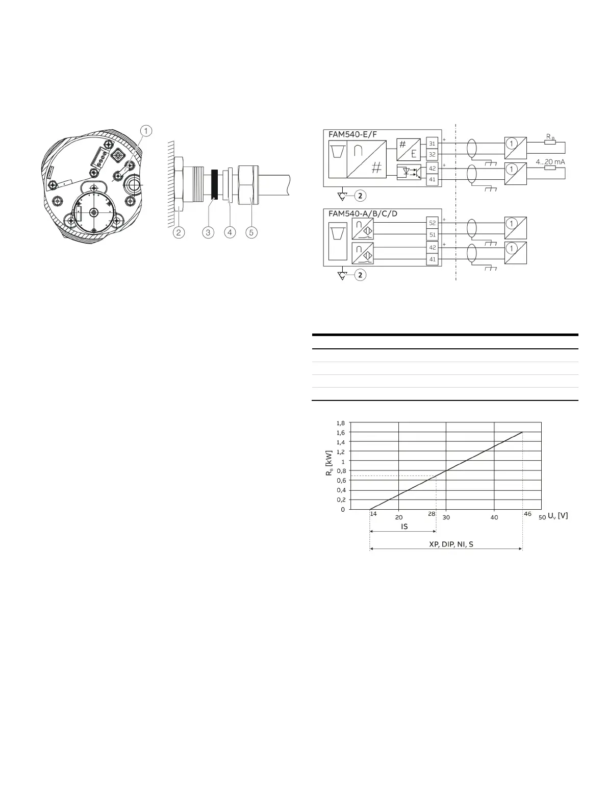
1 Strain relief
2 Adapter M25 × 1.5 / ½“-NPT
3 Gasket
4 Sleeve
5 Union nut
Figure 5: Connection using a flameproof cable gland
The outside diameter of the unshielded connection cable must
be in a range from 8.0 to 11.7 mm (0.3 to 0.5 in).
The cable gland must be dimensioned accordingly.
After installing the cable in the gland, tighten the union nut to a
torque of 3.25 Nm (2.40 lbf/ft).
Use an additional strain relief device in the housing to secure the
connection cable.
Electrical connections
1 FM Approved IS Barrier 2 Potential equalization
Figure 6: FM / cCSAus electrical connection
Terminal Function
31 / 32 Power supply / current output / HART output
41 / 42 Binary output
Alarm signaling unit (min.)
51 / 52 Alarm signaling unit (max.)
Figure 7: Terminals 31 / 32, power supply / load
U
V
Power supply
R
B
Maximum permissible load in the power supply (z. B. indicator)
The minimum voltage U
V
= 0 V is based on a load of 0 Ω.
 Loading...