48
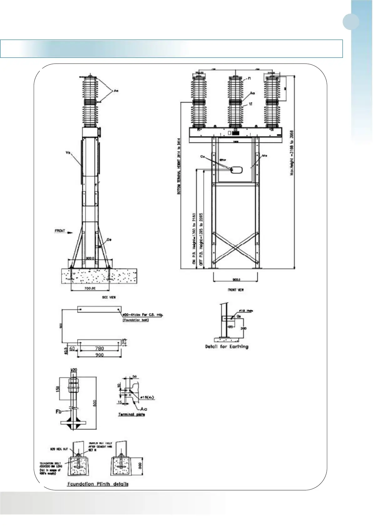
Fig. 1b. Standard General Arrangement Drawing
of VBF Breaker (with breaker structure)
Total weight 800Kgs approx.
Creepage distance of bushing insulator 900 mm
Paint shade for control cabinet : RAL 7035
Insulator colour : Brown
Cs Position indicatior ON-OFF,Mech Counter
Vs Supporting structure (Galvanised steel structure)
Ms Control cubicle with spring drive
VCTs CT Supporting structure (Galvanised steel structure)
Ge Earthing point (Galvenising Bus.)
Vi Supporting insulator column
Fb Foundation bolt (M20)
Aa Terminals(Al.alloy)
Fl Interrupting chamber
Note: Mounting holes for mounting of CT on CT Structure
are 450 X 450
Drawings