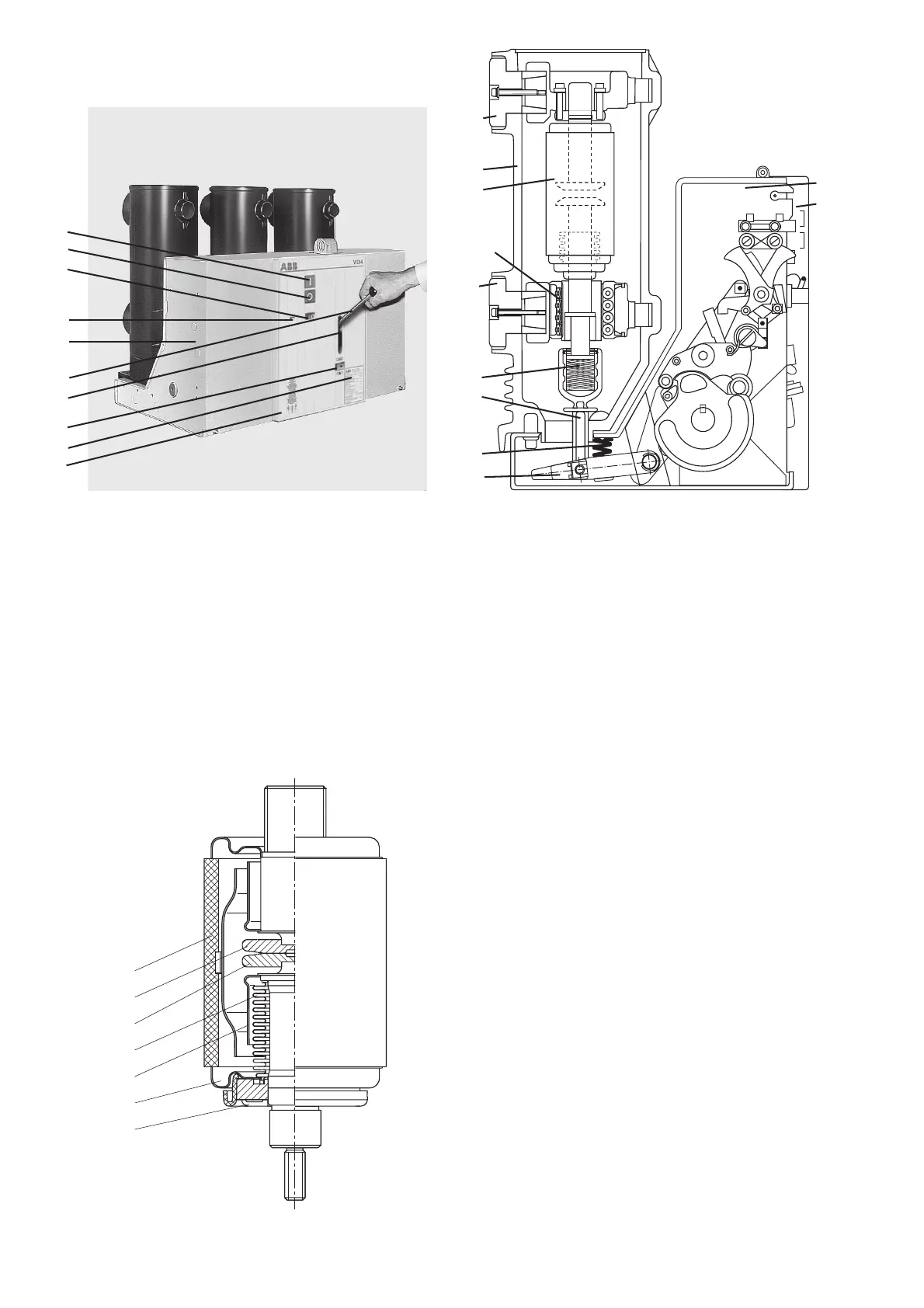
14
Figure 3/3: Partial section of a vacuum interrupter,
simplified schematic diagram
(Details vary according
to the specified switching duties)
15.1 Insulator
15.2 Fixed contact
15.3 Movable contact
15.4 Metal bellows
15.5 Screen
15.6 Guide
15.7 Interrupter lid
Figure 3/2: Sectional view of a vacuum circuit-breaker,
type VD4, schematic diagram
1 Mechanism enclosure
1.1 Front plate, removable
12 Insulating material pole tube
13 Upper breaker terminal
14 Lower breaker terminal
15 Vacuum interrupter
16.2 Roller contact
17 Contact force spring
18 Insulated coupling rod
19 Opening spring
20 Shift lever pair
Figure 3/1: Circuit-breaker front with controls and annunciations
1 Mechanism enclosure
1.1 Front plate
2 ON push-button
3 OFF push-button
4 Position indicator
5 Operating cycle counter
6 Recess for charging lever 9
7 Rating plate
8 Charging condition indicator
9 Charging lever
15.1
15.2
15.3
15.4
15.5
15.7
15.6
1.1
8
5
4
3
2
6
7
1
9
1
1.1
13
12
15
14
17
18
19
20
16.2

 Loading...


