EasyManuals Logo

ABB VD4 Series User Manual

ABB VD4 Series
28 pages
To Next Page IconTo Next Page
To Previous Page IconTo Previous Page
Page #15 background imageLoading...
Page #15 background image
15
37
31
38
6
35
33
34
36
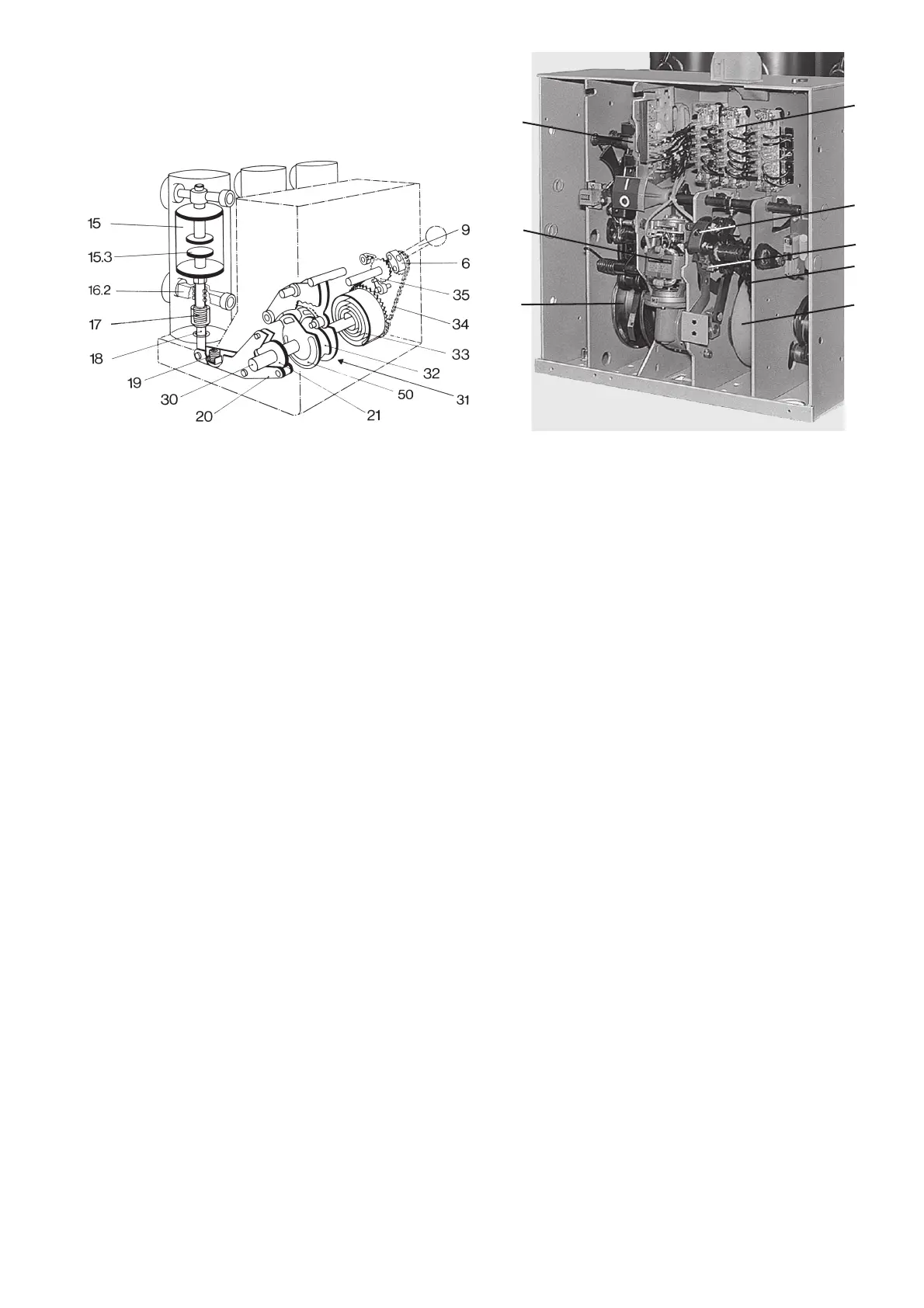
Figure 3/4: Basic structure of the stored-energy spring mechanism
6 Recess
9 Charging lever
15 Vacuum interrupter
15.3 Movable contact
16.2 Roller contact
17 Contact force spring
18 Insulated coupling rod
19 Opening spring
20 Shift lever pair
21 Cam disk
30 Drive shaft
31 Release mechanism
32 Stop disk
33 Drum with spiral spring
34 Chain drive
35 Ratchet wheel
50 Left-hand control cam
Figure 3/5: View of the stored-energy spring mechanism and auxiliary
equipment with the front plate removed
6 Recess for charging lever 9
31 Release and control mechanism on the drive shaft
33 Drum with spiral spring
34 Chain drive
35 Ratchet wheel
36 Charging motor
37 Release and control mechanism area
38 Auxiliary switch block

Table of Contents

Other manuals for ABB VD4 Series

Questions and Answers:

Question and Answer IconNeed help?

Do you have a question about the ABB VD4 Series and is the answer not in the manual?

ABB VD4 Series Specifications

General IconGeneral
Operating mechanismSpring-operated mechanism
InstallationFixed or withdrawable
Rated frequency50/60 Hz
Poles3
Rated currentUp to 4000 A
StandardsIEC 62271-100
InsulationVacuum
ApplicationMedium voltage
Control voltage24-240 V AC/DC
WeightDepending on the specific model

Related product manuals