A-80 UHF SERVICE MANUAL
- 40 -
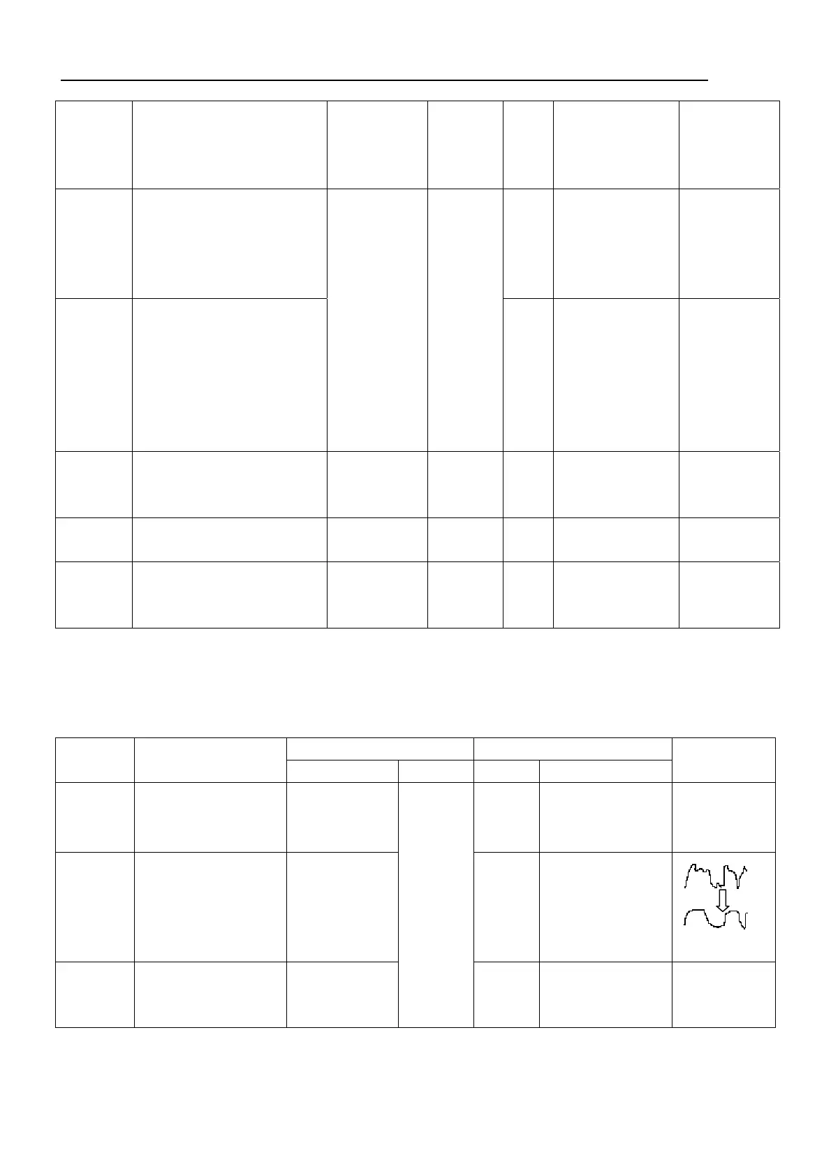
1 . Band
pass-filter
1) CH:RX center
2)Tra generator output -40dBm
Connect the spectrum analyzer to
L103 terminal
Tra generator
Spectrum
Analyzer
ANT
L103
TC301
TC300
Adjust the frequency
so that it becomes the
spectrum waveform
shown in fig1.
2 . Audio
Lever
1)CH:Rx center
SSG output:-80dBm(501μV)
MOD:1KHz
DEV:±3.0KHz(Wide)
±1.5KHz(Narrow)
L35
Adjust to the
maximum AF lever
3.Sensitiv
ity
1)CH:RX center
CH:RX LOW
CH:RX HIGH
SSG output:-116dBm(0.35μV)
MOD:1KHz
DEV:±3.0KHz(wide)
±1.5KHz(narrow)
SSG
Oscilloscope
AF.V.M
Distortion meter
Antenna
Speaker
Check
SINAD:12dBor
higher
4. Squelch
Level ( PC
mode)
1)CH:RX center
MONI:on
PC
key
Level 9
Adjust to close the
squelch
The squelch
must be closed
2)Level 9
SSG output:-117dBm
3)Level 3
SSG output :-125dBm(0.126μV)
Level 3
Adjust to close the
squelch
The squelch
must be closed
Transmitter section
Measurement Adjustment
Item
Condition
Test equipment Terminal Parts Method
Specification/
Remark
1.Transmit
(PC mode
1)CH:TX center
PTT:On
F. counter PC key
Adjust to center
frequency
Within ±100Hz
2. DQT/QT
Balance
(PC
MODE)
1)CH: TX Center Modulation
Analyzer or linear
Detector
( LPF3kHz)
Oscilloscope
VR100 Rectify the waveform
to square wave
3. Power
(PC mode)
1)CH: TX low
Battery terminal: 7.5V
PTT: ON
Power meter
Ammeter
Antenna
Adjust to 4.1W
±0.1W