S1 Service manual
13
The transmit signal obtained from the VCO buffer amplifier Q9, is amplified by Q10. This
amplified signal is passed to the power amplifier, Q18 and Q29, which is capable of producing
up to 1W of RF power.
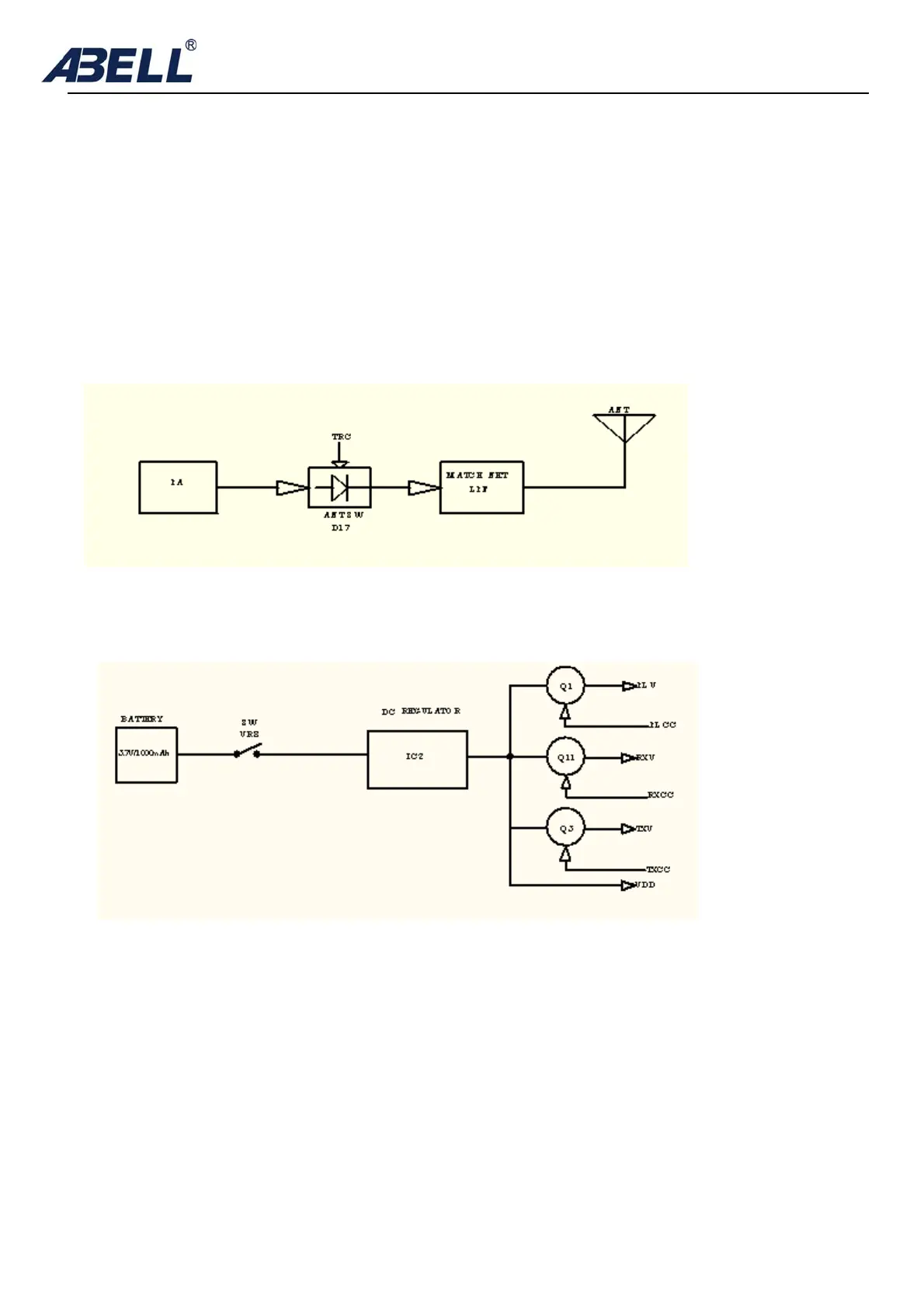
4) ANT switch and LPF
The RF amplifier output signal is passed through a low-pass filter network and a transmit
/receive switching circuit before it is passed to the antenna terminal. The transmit /receive
switching circuit is comprised of D17 and D17 turned on (conductive) in transmit mode and off
(isolated) in receive mode.
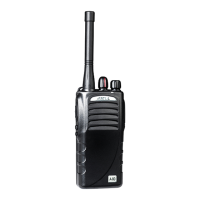
5.Power supply
A 3.7V reference power supply for the control circuit is derived from an internal battery
1000mAh Li-ion by IC3. This reference supply VDD is 3V which is used to provide a 3V
supply in transmit mode [TXC], a 3V supply in receive mode [RXC], and a 3V supply for VCO
for [PLC]
6. Control system
The IC5CPU operates at 32.768 MHz. This oscillator has a circuit that shifts the frequency
according to the EEPROM data.