2-16 Chapter2
BE6
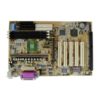
Figure 2-10. How to connect an ATA/66
Cable to the Motherboard
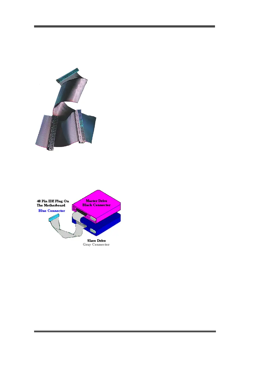
Figure 2-9. Photo of an Ultra
ATA/66 Conductor Cable
and host systems. The Ultra ATA/66 protocol and commands are designed to be compatible
with existing ATA (IDE) devices and systems. Although a new 40-pin, 80-conductor cable is
required for Ultra ATA/66, the chip set pin connector remains the same at 40. Hard drives
that support Ultra ATA/66 also support Ultra ATA/33 and legacy ATA (IDE) specifications.
There are four requirements for attaining Ultra ATA/66:
*The drive must support Ultra ATA/66.
*The motherboard and system BIOS (or an add-in
controller) must support Ultra ATA/66.
*The operating system must support Direct Memory
Access (DMA); Microsoft Windows 98 and Windows
95B (OSR2) support DMA.
*The cable must be 80-conductor; the length should not
exceed 18 inches. If all the above requirements are met,
you can enjoy the Ultra ATA/66 features of your
computer system.
How to install the Ultra ATA/66 Cable Assembly:
&
The
BLUE
connector
MUST
be plugged
into the motherboard or your system will not
work.
&
Each connector on the Ultra ATA/66
cable assembly has a small polarization tab
centrally located on the body of the plastic.
This fits into the matching slot on the mating
plugs on the motherboard and the drives,
thus assuring positive mating (pin #1 to pin
#1)
&
The red line on the cable should be aligned with pin #1. On the drives this will result in the
red line facing the power connector. Attach the BLUE connector to the appropriate 40 pin
IDE plug on the motherboard.
&
Attach the BLACK connector to the mating plug on the master hard drive. Attach the
GREY connector to the mating plug on the slave drive (secondary hard drive, CD ROM,
or tape drive). Please refer figure 2-10.