Hardware Setup 2-11
• Pin-6/8: PWR-ON
Connects to the Power Switch cable of chassis front panel.
• Pin-16/18/20: PWR-LED
Connects to the Power LED cable of chassis front panel.
• Pin-22/24: KEYLOCK
Connects to the Keylock cable (if there is one) of chassis front panel.
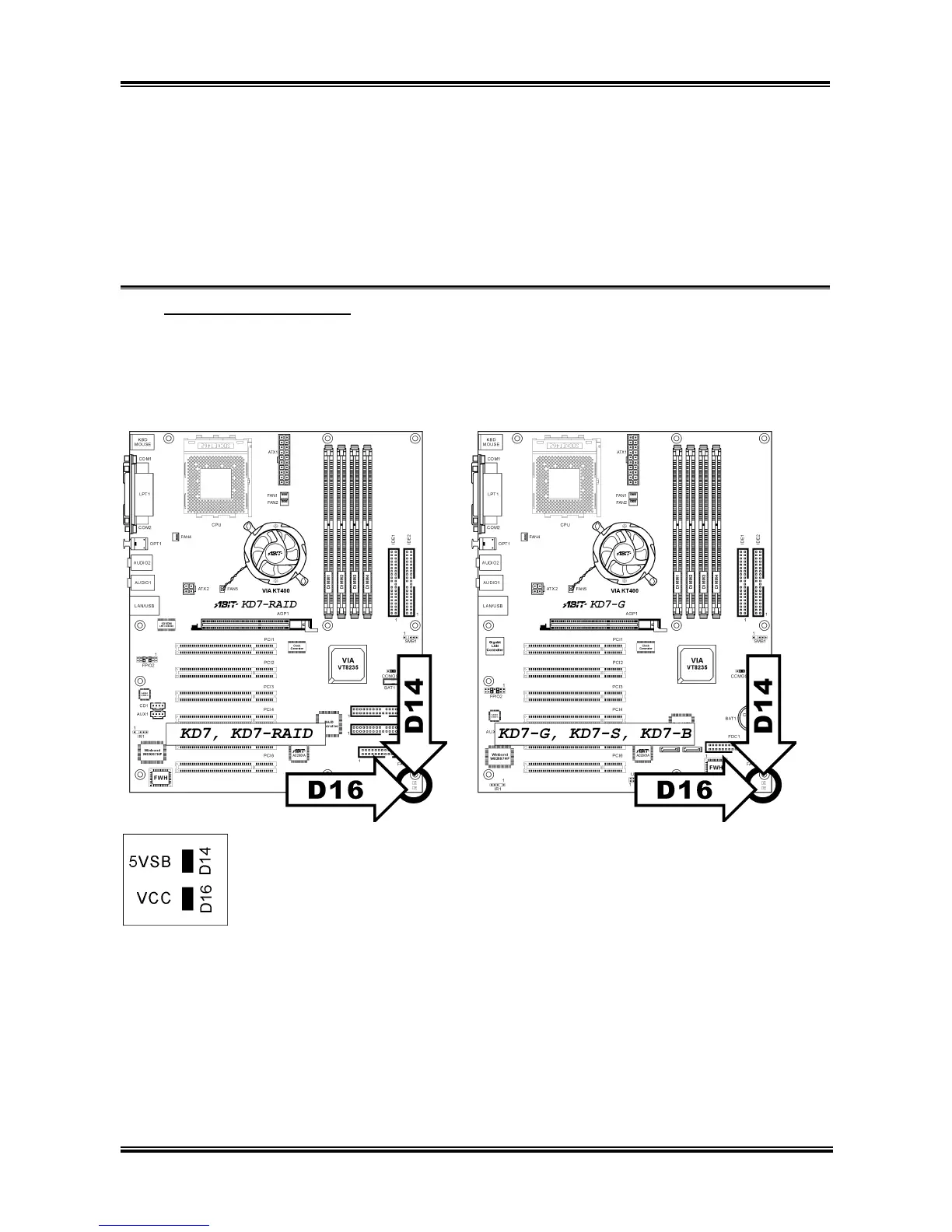
(8). D14/D16: Status Indicator
• D14 (5VSB): Stand By LED Indicator
This LED lights up when the power supply is connected with power source.
• D16 (VCC): Power on Indicator
This LED lights up when the system power is on.
User’s Manual