EasyManua.ls Logo

Abrams UG-1200 - User Manual

Abrams UG-1200
2 pages
Print Icon
To Next Page IconTo Next Page
Loading...
Specificaons
120.6mm
32.2mm
14.3
LED: 3W*12 Spilt/Dual
LEDs per head : 12
Voltage : 10-30VDC
Flash paerns : 69
Color : Color 1* Color 2
Proper installaon of this product requires the installer to have a good
understanding of automove electronics, systems and procedures.
Failure to use specified installaon parts or hardware will void the
product warranty.
For this product to operate at opmum efficiency, a good electrical
connecon to chassis ground must be made.
It is recommend that these instrucons be stored in a safe place and
referred to when performing maintenance or reinstallaon of this
products.
Do not install and/or operate this safety product unless you have read
and understand the safety informaon contained in this manual.
This document provides all the necessary informaon to allow your product to be properly and
safely installed. Before beginning the installaon and operaon of your new product, the
installaon technician and operator must read this manual completely.
P52 Quad 75FPM is Factory Default.
Phase Operaon: Ph1= Phase 1 / Ph2=Phase 2
Phase 1 (Ph1) flashes simultaneously with Ph1
Phase 2 (Ph2) flashes simultaneously with Ph2
Operaon
Default
Apply BLUE to BLACK wire:
-Less than1 sec. for next paern
-Between 1-3 sec. for previous paern
-Between 3-5 sec. for Factory Default
-More than 5 sec. for Last Paern
INSTALLAT ION AN D CONFI GURATION MAN UAL INSTALLAT ION AN D CONFI GURATION MAN UAL
MODEL#: UG-1200
ABRAMS INSTALLATION AND CONFIGURATION MANUAL V.1.1
WWW.ABRAMSMFG.COM | INFO@ABRAMSMFG.COM
01
IMPORTANT! PLEASE READ THROUGH ALL
PROVIDED INSTRUCTIONS AND ANY LISTED
WARNINGS IN REGARDS TO PRODUCT USE.
Abrams Ultra Grill Lights
844.9.ABRAMS
info@AbramsMFG.com
www.AbramsMFG.com
Abrams Ultra Grill Lights
844.9.ABRAMS
info@AbramsMFG.com
www.AbramsMFG.com
Question and Answer IconNeed help?

Do you have a question about the Abrams UG-1200 and is the answer not in the manual?

Summary

Abrams Ultra Grill Lights Installation Manual

Product Specifications

Details product specifications including LED count, voltage, flash patterns, and color options.

Default Operation Settings

Describes the factory default flash pattern and phase operation.

Operation Mode Control

Explains how to change flash patterns using the BLUE wire and specific time durations.

Wiring and Mounting Guide

Mounting and Wiring Instructions

Provides details on mounting the unit and connecting wires for synchronization and power.

Recommended Operating Environment

Specifies the recommended ambient temperature and humidity for optimal operation.

Wire Color Functions

Details the function of each wire color: RED, BLACK, BLUE, YELLOW, and WHITE.

Troubleshooting

Troubleshooting Common Issues

Guides users on diagnosing and resolving potential issues with the product's function.

Overview

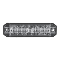
The Abrams Ultra Grill Lights are a safety product designed for automotive applications, providing high-visibility lighting with a range of customizable flash patterns. This manual outlines the installation, configuration, and operational features of the UG-1200 model.

Function Description

The Abrams Ultra Grill Lights are intended to enhance vehicle visibility through various flashing patterns and steady burn options. They are designed for use as stop, turn, brake, or tail lights, and can be synchronized with multiple units for coordinated lighting effects. Proper installation is crucial for optimal performance and to maintain product warranty.

Important Technical Specifications

  • LED Type: 3W*12 Split/Dual
  • LEDs per head: 12
  • Voltage: 10-30VDC
  • Flash Patterns: 69
  • Color: Color 1* Color 2 (indicating dual color capability)
  • Dimensions: 120.6mm (length) x 32.2mm (width) x 14.3mm (height)
  • Recommended Operation Environment:
    • Ambient Temperature: -30 to 50°C
    • Relative Humidity: 10 to 85%, non-condensing

Usage Features

The Abrams Ultra Grill Lights offer extensive customization for their operation, primarily through wiring connections and pattern selection.

Default Settings

The factory default setting is "P52 Quad 75FPM" (Flash Per Minute).

  • Phase Operation:
    • Phase 1 (Ph1) flashes simultaneously with Phase 1 units.
    • Phase 2 (Ph2) flashes simultaneously with Phase 2 units.

Wiring and Operation

  • RED wire: Positive connection (requires a 2A fuse).
  • BLACK wire: Negative connection.
  • BLUE wire: Pattern Switch.
    • Applying BLUE to BLACK wire for:
      • Less than 1 second: Next pattern.
      • Between 1-3 seconds: Previous pattern.
      • Between 3-5 seconds: Factory Default pattern.
      • More than 5 seconds: Last pattern.
  • YELLOW wire: Synchronized Function.
    • Connecting all YELLOW wires together enables synchronization across multiple units. A maximum of 8 units can be synchronized.
  • WHITE wire: Stop/Turn/Brake/Tail Light Switch (Optional).
    • Applying WHITE to RED (+) wire activates a steady burn pattern, suitable for stop, turn, brake, or tail light functions.

Flash Pattern Table

The device supports 69 distinct flash patterns, categorized by single, double, triple, and quad flashes, as well as modulation and steady burn options. Each pattern can be configured for synchronous or alternating operation, and specific color combinations (Color 1, Color 2, Color 3, Color 4) are indicated. The table also specifies whether synchronization is supported for each pattern.

Examples of Flash Patterns:

  • Pattern 1 (Default): Single 75FPM Ph1 Color 1 Synchronous Color 3 (YES Sync)
  • Pattern 3: Single 75FPM Ph1 Color 1 Alternately Color 4 (YES Sync)
  • Pattern 19: Double 75FPM Ph1 Color 1 Synchronous Color 3 (YES Sync)
  • Pattern 46: Quad 75FPM Ph1 Color 1 Synchronous Color 3 (YES Sync)
  • Pattern 64: Modulation (Color 1 Synchronous Color 3) Alternately (Color 2 Synchronous Color 4) (NO Sync)
  • Pattern 68: Steady burn-Color 1 & 3 (NO Sync)

Maintenance Features

  • Storage of Instructions: It is recommended to store these instructions in a safe place and refer to them when performing maintenance or reinstallation of the product.
  • Troubleshooting:
    • Power Connection: Ensure the power source is correctly joined and there is no short-circuited power.
    • Power Switch: Verify that the power switch is turned to "ON" position.
    • Electrical Connection: For optimum efficiency, a good electrical connection to chassis ground must be made.
  • Warranty: Failure to use specified installation parts or hardware will void the product warranty.
  • Safety: Do not install and/or operate this safety product unless you have read and understand the safety information contained in this manual.

Installation Requirements

  • Installer Knowledge: Proper installation requires the installer to have a good understanding of automotive electronics, systems, and procedures.
  • Included Items: Each package includes:
    • LIGHT HEAD *1
    • Screw *2
    • Manual *1
    • Mounting Gasket *1
  • Pre-installation: Before beginning the installation and operation of your new product, the installation technician and operator must read this manual completely.

Abrams UG-1200 Specifications

General IconGeneral
BrandAbrams
ModelUG-1200
CategoryAutomobile Accessories
LanguageEnglish

Related product manuals