19
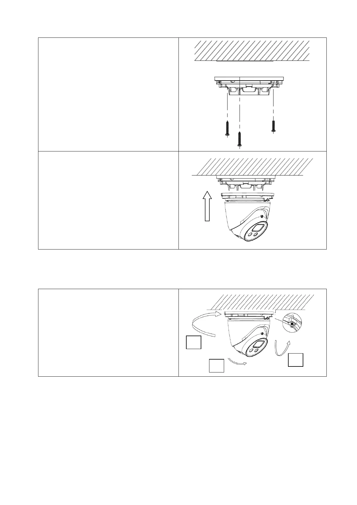
3 Use the supplied drilling template to mark
the mounting holes. Depending on the
substrate, please use suitable dowels and
screws. Then fix the bottom plate.
4. For cable routing, drill a suitable hole in
the middle of the floor panel in the
ground, or use the optional box hole on
the floor panel for side cable routing (in
this case, the cable must be routed
sideways before installing the floor panel).
5. Then attach the camera head with fixing
cap and fix the fixing screw lightly.
3.3 Alignment of camera
A: Pan
B: Tilt
C: Rotation
Tighten the fixing screw to the desired
orientation of the camera head.
B
C