28
3. Connections and functions
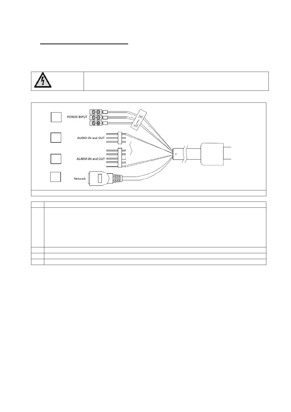
3.1 Connections and controls
ATTENTION!
Before you begin the installation, make sure that the supply voltage and the
nominal voltage of the camera match.
Nr. Beschreibun
1 Power supply connector, 24 V AC
Pin assignment:
black: 24 V AC
yellow/green: GND
red: 24 V AC
2
udio input / outpu
3 2 x Alarm input, 1 x Alarm outpu
4 Network connector, RJ45
PoE+, 30 Watt
1
2
3
4