– 39 –
LED:
Signal: green steady signal
Meaning: An action has been
completed successfully
LED:
Signal: red steady signal
Meaning: Error
3 seconds
3 seconds
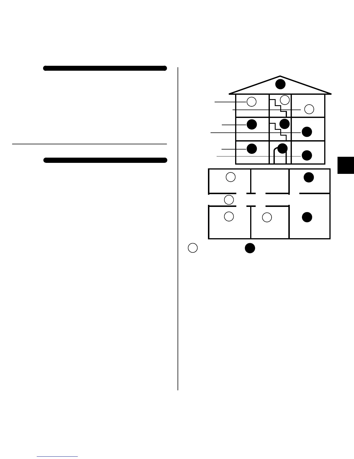
acc. DIN 14676)
Bedroom
Bath Kitchen
Living room
Childrens
room
Childrens
room
RM
RM
RM
RM
RM
RM
Bedroom
Kitchen
Living room
Boiler/
utility room
Workshop
Children’s room
RM
RM
RM
RM
RM
RM
RM
RM
RM
RM
RM
Fig. 2
RM
RM
at least optimal
(e.g. fan, ventilation...) or bathrooms
- Unit is suitable for kitchens, if false alarms due to
steam can be ruled out
- At the highest installation position on the ceiling in the
middle of the room (not on walls )
- Minimum distance of 50 cm from walls, furniture,
lamps
- Monitored area maximum 60 m
2
with maximum ceiling
height of 6 m
- Distance between two devices maximum 15 m
- Corridor length maximum 7.5 m
- Not onto the ceiling beam for ceiling beams with a
height of >20 cm, but 1 device per intermediate space
up to a maximum of 36 m
2
in surface area
- For ceiling beams with a height of <20 cm, a detector
at the centre of the room (also possible on ceiling
beam)
GB