EV/DV300 Series Power Meter
V:2.0 Revised October 2018
The receiving device recalculates a CRC during receipt of the message, and compares the
calculated value to the actual value it received in the CRC field. If the two values are not equal,
an error results.
The CRC is started by first pre-loading a 16-bit register to all 1’s. Then a process begins of
applying successive 8-bit bytes of the message to the current contents of the register. Only
the eight bits of data in each character are used for generating the CRC. Start and stop bits,
and the 51 EV/DV Series parity bit, do not apply to the CRC. During generation of the CRC,
each 8-bit character is exclusive ORed with the register contents. Then the result is shifted in
the direction of the least significant bit (LSB), with a zero filled into the most significant bit
(MSB) position. The LSB is extracted and examined. If the LSB was a1, the register is then
exclusive ORed with a preset, fixed value. If the LSB was a 0, no exclusive OR takes place. This
process is repeated until eight shifts have been performed. After the last (eighth) shift, the
next 8-bit byte is exclusive ORed with the register current value, and the process repeats for
eight more shifts as described above. The final contents of the register, after all the bytes of
the message have been applied, is the CRC value. When the CRC is appended to the message,
the low-order byte is appended first, followed by the high-order byte.
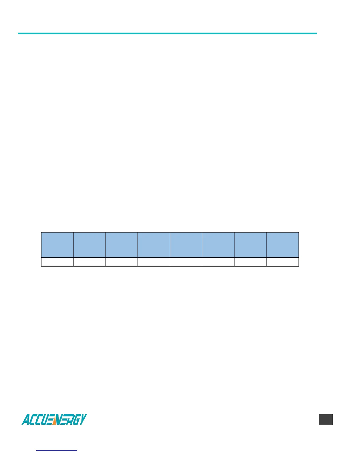
4.2 Format of Communication
Explanation of frame (Hex)
Table 4.3 Frame example
In Table 4.3, the meaning of each abbreviated word is,
Start register address high (high byte)
Start register address high (low byte)
Number of register (high byte)
Number of register (low byte)
 Loading...