Installation & Operation Manual - Model AVT4000
Contents of this Manual are Subject to Change Without Notification Page 14
SECTION 5 – WIRING
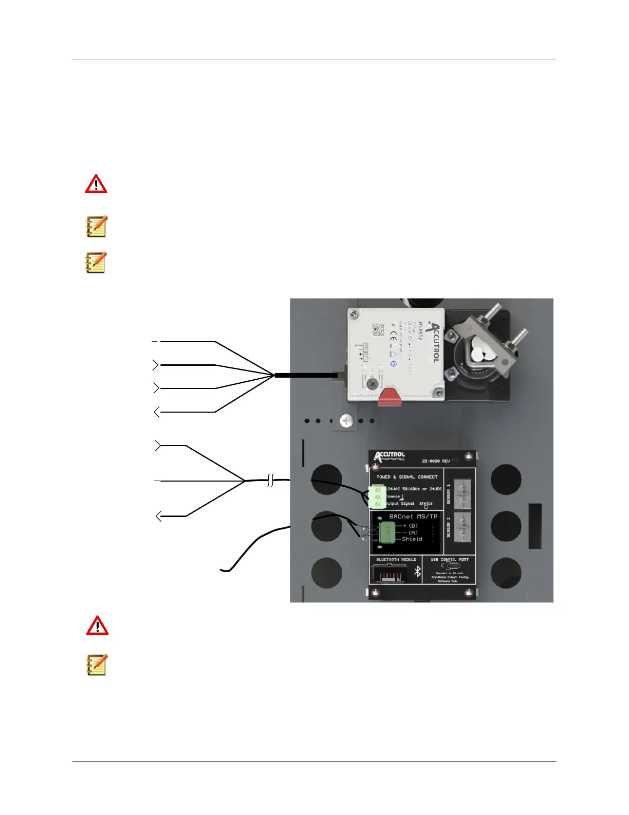
5.1 AVT4000 Transmitter Wiring Instructions
1. Remove cover
2. Route cables through the strain relief fitting into the enclosure
3. Connect wires to appropriate terminals and secure terminal screws
4. Insert the ratcheting strain relief over cable(s) and push down until snug.
5. Reinstall cover.
CAUTION: Maintain polarity if power source is used for multiple devices, otherwise
equipment may be damaged.
Note: Connections will vary based on application. For detailed wiring instructions, use
this drawing in conjunction with the job specific wiring diagrams.
Note: Switch or circuit breaker must be included in the installation and located where it
is easily reached and marked as disconnecting device for the equipment.
WARNING: Do not use enclosure as junction box for other equipment.
Note: If a direct conduit connection is required., remove strain relief fitting and replace
with a .875 (22mm) conduit fitting. (Provided by others)
 Loading...