EasyManuals Logo

Accutrol AccuValve AVT6000 User Manual

Accutrol AccuValve AVT6000
43 pages
To Next Page IconTo Next Page
To Previous Page IconTo Previous Page
Page #15 background imageLoading...
Page #15 background image
Installation & Operation Manual - Model AVT6000
Contents of this Manual are Subject to Change Without Notification Page 15
SECTION 5 WIRING
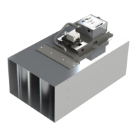
5.1 AVT6000 Transmitter Description
5.2 Wiring Instructions
1. Remove cover and route cables through strain relief fitting into enclosure.
2. Remove terminal block plug(s) and connect wires to the appropriate terminals.
3. Secure terminal screws and reinstall plug(s).
4. Insert the ratcheting strain relief over cable(s) and push down until snug.
5. Reinstall cover and secure thumb screw.
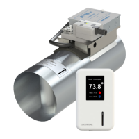
5.3 Transmitter Wiring Diagram: The figure below is shown with the optional BACnet and
AccuNet modules installed and the remote monitor connected. For more details regarding the
AccuNet, reference Appendix B.
24 vAC
24 vDC
or
Analog Input
BMS Controller /
Signal Receiving
Device
+
Common
Power Source
BACnet MSTP Bus
AccuNet Bus
Ref Appendix C
AVT6000 Transmitter
Remote
Monitor
Factory
Cable
Clear Tubing
Connected to Sen 1
Black Tubing
Connected to Sen 2
CAUTION: Maintain polarity if power source is used for multiple devices, otherwise
equipment may be damaged.
Captive Thumb Screw for Removing/Securing Cover
Cable Entry
with Ratcheting
Strain Relief
NOTE: If a direct conduit connection is
required, remove strain relief fitting and
replace with a .875 (22mm) conduit
fitting. (Provided by Others)
Connection from optional monitor using
factory supplied cable.
Alternate
Cable Entry
Cover Tab Slot

Questions and Answers:

Question and Answer IconNeed help?

Do you have a question about the Accutrol AccuValve AVT6000 and is the answer not in the manual?

Accutrol AccuValve AVT6000 Specifications

General IconGeneral
BrandAccutrol
ModelAccuValve AVT6000
CategoryControl Unit
LanguageEnglish

Related product manuals