DC Inverter U-match Series for R410A Unitary Split Air Conditioner
⑦. The external power cords, the thermostat wires and outdoor unit must not
collide with any metal beam or edge on the ceiling, or touch any metal burrs or
sharp metal edge around.
⑧. Connect wires correspondingly by referring to the circuit diagram labeled on
the unit or electric box. Screws must be tightened up. Slipped screws must be
replaced by specialized flat-head screws.
⑨. Wiring terminals should be connected firmly to the terminal board. Loose
connection is forbidden.
⑩. The wire gauge of power cords should be large enough. Damaged power
cords or other wires must be replaced by specialized wires. Wiring work must
be done according to national wiring rules and regulations.
⑪. This outdoor unit has a heating four-way valve.
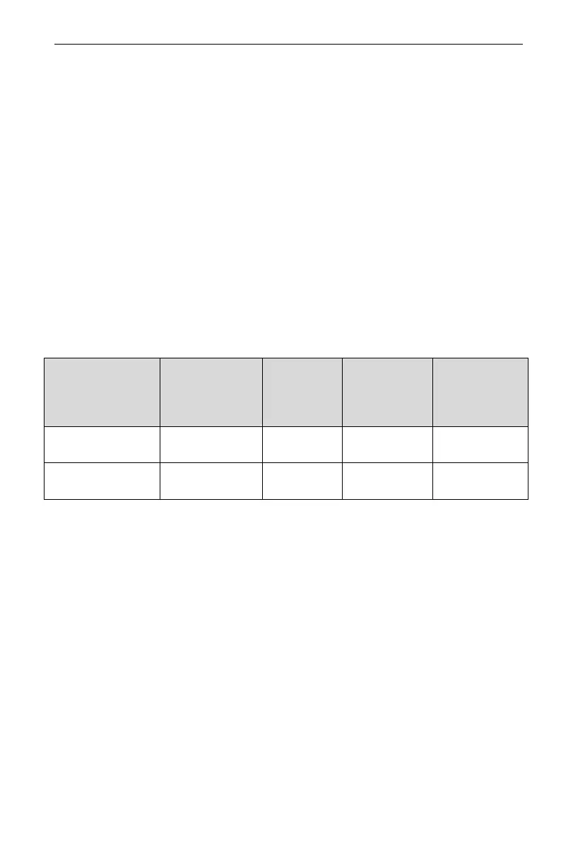
3.3.2 Electrical Parameters
Model Power supply
Fuse
capacity
(A)
Maximum
over-current
protection
Minimum
circuit
ampacity
FXD-ACD36
208/230V-
35 35 24
FXD-ACD60
208/230V-
45 45 35
3.3.3 Connection of Power Cords and Thermostat Wires
(1) For solid wires (as shown below):
1) Use wire cutters to cut off the wire end and then peel away about 25mm
of the insulation layer.
2) Use a screwdriver to unscrew the terminal screw on the terminal board.
3) Use nippers to bend the solid wire into a ring that fits the terminal screw.
4) Form a proper ring and then put it on the terminal board. Use a
screwdriver to tighten up the terminal screw.
(2) For strand wires (as shown below):
1) Use wire cutters to cut off the wire end and then peel away about 10mm
of the insulation layer.
2) Use a screwdriver to unscrew the terminal screw on the terminal board.