33
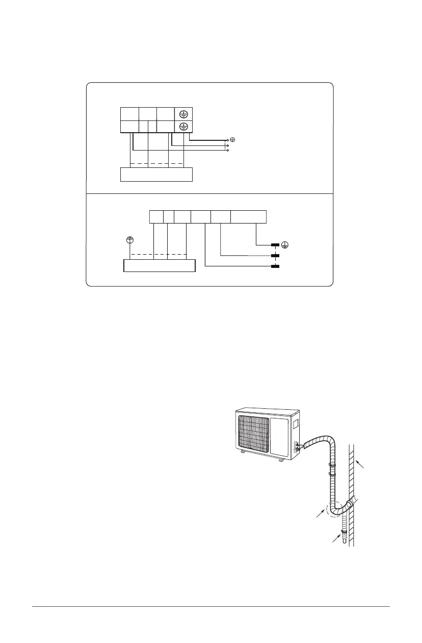
Step 5: Wiring of the unit
• Remove the wire clip; connect the power connection wire and signal control wire to the wiring
terminal according to the color; fix them with screws.
Outdoor unit connection
Indoor unit connection
L2L1
23N(1)
L2
L1
POWER
white
(blue)
white
(blue)
black(brown)
red
(brown)
black
yellow-
(
green
)
green
yellow-
(
green
)
green
9K-12K:
L1
L2
POWER
L1 L2
N(1)
2 3
G
yellow-
(
green
)
green
Indoor unit connection
white
(blue)
black
red
(brown)
black
(brown)
white
(blue)
yellow-
(
green
)
green
18K-24K:
Note: this wiring diagram is for reference only, please always refer to the one on the actual unit.
• Fix the power connection wire and signal control wire with wire clip.
Notes:
• After tightening the screw, pull the power cord slightly to check if it is solid.
• Never cut the power connection wire to extend or shorten it.
Step 6: Pipe arrangement
• The pipes should be placed along the wall, slightly
bent and if possible be hidden. The minimum
bending semi diameter is 10 cm.
• If the outdoor unit is higher than the wall hole,
you must set a U-shaped curve in the pipe before
pipe goes into the house, in order to prevent rain
from getting in.
U-shaped curve
wall
drain hose