2
ACDC Motorized Solutions Pty. Ltd.
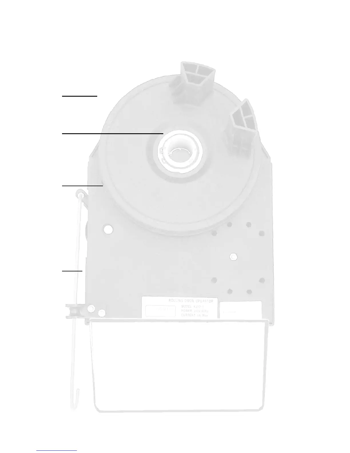
RollerGlide Rolling Door Operator
Installer fitting instructions
Introduction
If this is your first installation of a RollerGlide automatic rolling door operator, please
read and fully understand the instructions before proceeding. For more information
and product updates visit our Web site http://www.acdcms.com.au.
Check contents in the installation kit
RollerGlide automatic rolling door operator
Power lead
Two remote transmitters
Owner manual & Warning label
Extension forks & weight bars (x2)
Tools required (see figure 1)
Extension socket set, to fit the existing U-bolts on the door
• A 14mm spanner or socket to tighten the RollerGlide bolts
• Door support or prop
• A ladder to reach the top of the door
• Rope or strap to secure door curtain
• Lifting bar (piece of strong steel pipe) to fit inside the door support shaft to aid
lifting
• Small bladed screwdriver to adjust internal controls
• Use a helper if possible to assist with the installation
Checks (see figure 1)
• The door must be in good working order
• Some doors require the fitting of a weight bar that sits in the bottom of the
door to provide a small amount of extra weight; this stabilizes the bottom of
the door when closing and provides inertia to allow the door to fully close.
They are usually a rectangular length of mild steel weighing about 2kg
• Tighten the U-bolt clamp on the opposite end to where the RollerGlide is to
be installed
• All existing door locks should be removed or warranty will be void
• The RollerGlide is fitted between the door mounting bracket and the door
roller. The minimum distance needed is 70mm. If the distance is not sufficient
the mounting bracket may need to be adjusted.
• The unit is shipped to fit a right hand installation
(Viewed from inside the garage)
• Use the service lever to disengage the unit so that the large fork wheel freely
rotates
• Changing from right to left mounting (see figure 3)
• The motor power plug is moved from socket A to socket B changing the
operator from right to left hand operation