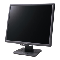
Assemble the hinge cover into both two sides
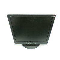
Assemble the stand upper side to the rear cover
through the way of screwing 4 screws till both
units firmly attached.
(No1~4 Screw Size=M4x12;
Torque=12~ KGFxCM).14~
Put a n he ssembled nit nd
ress on force echanisms ocked nd irmly
attached
.
front bezel o t a u a
pmlaf
Take a key function board to hook with rear
bezel and connect to key function cable.
Use a Phillips-head screwdriver screwed the
No.1~2 screws. (No1~2 screw size=M3x6;
Torque=5~6KGFxCM).
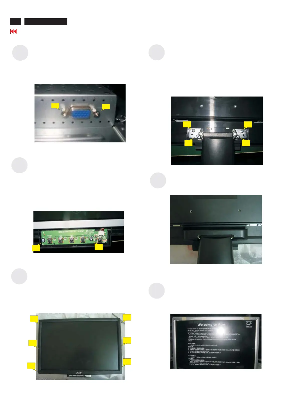
Use a Hex-head screwdriver screwed the
D-SUB connectors (No.1~2 Hex Nut screws
Size=M3x8;Torque=5~6KGFxCM).
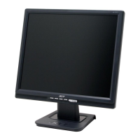
Stick a screen card on the front bezel with two
tapes.
S17
S16
S15
S14
S13
S12
1
2
3
4
4. Assembly and Disassembly Procedures (continued)
1
2
1
2
1
2
3
1
2
3
14
Go to cover page
ACER AL1516W