- 20 -
15
10
5 1
6
11
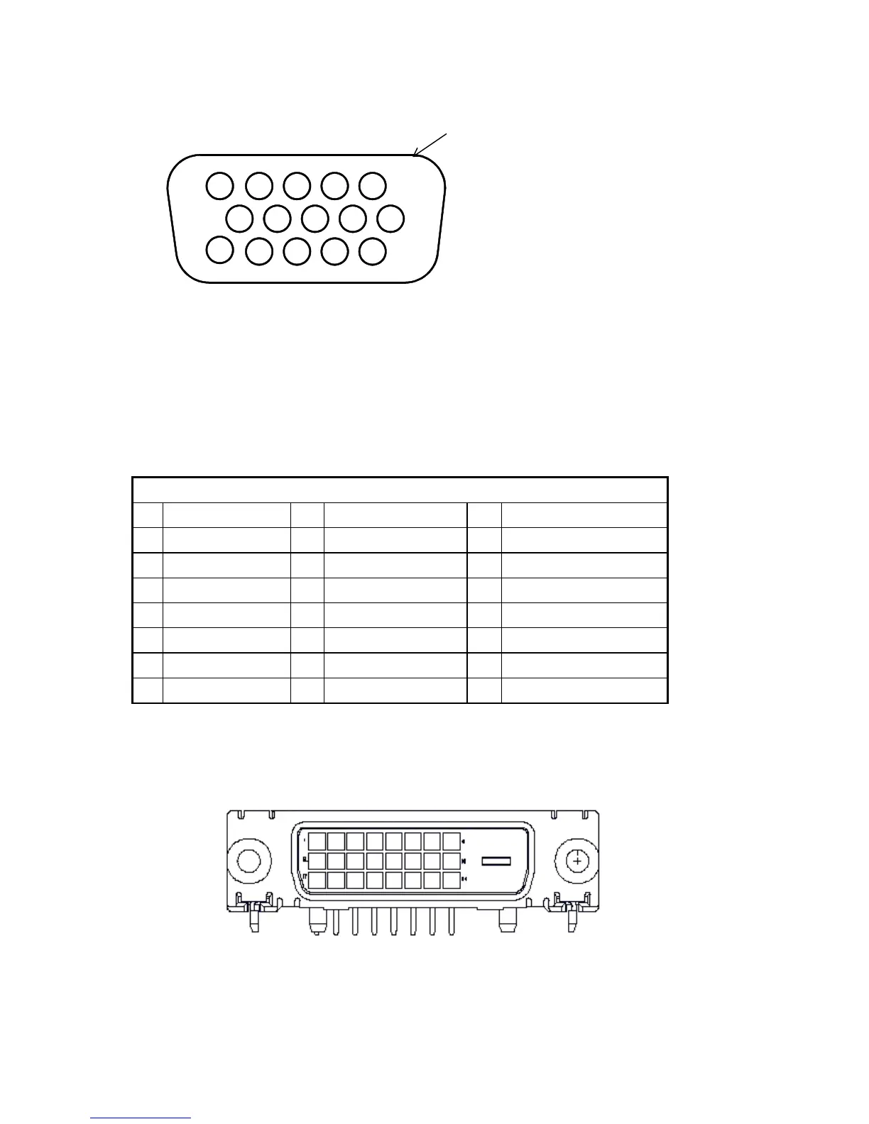
D-sub connector
Digital Video Input Connector : DVI – D (T.B.D)
Table 2.4.6 Pin assignment for DVI – D Connector:
Pin – Assignment of DVI –D connector :
1 TX2- 9 TX1- 17 TX0-
2 TX2+ 10 TX1+ 18 TX0+
3 Shield (TX2 / TX4) 11 Shield (TX1 / TX3) 19 Shield (TX0 / TX5)
4 NC 12 NC 20 NC
5 NC 13 NC 21 NC
6 DDC-Serial Clock 14 +5V power *) 22 Shield (TXC)
7 DDC-Serial Data 15 Ground (+5V) 23 TXC+
8 No Connect 16 Hot plug detect 24 TXC-
*) In case, the power of the PC unit is switched off and the power of the monitor is switched on, no
voltage may occur at pin 14.
Color of plastic parts: Blue (PC99)

 Loading...