Acer Service Manual
Chapter 3- CIRCUIT THEORY
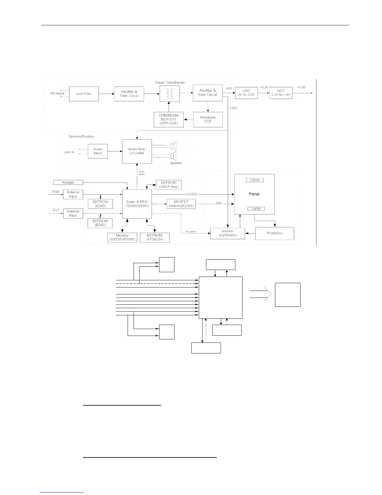
1. Monitor Block Diagram
The LCD Monitor contains an interface board, and inverter/power/Audio board, keypad board and flat
panel. In Inverter/power/Audio board, power section supplies +14V & +5V for Inverter/Audio and
Interface board used. The inverter section drives the backlight of panel and the DC-DC conversion.
2. Interface BOARD DIAGRAM
A/D&
Scaler&MCU
Red
Green
Hsync
Vsync
Blue
VGA
DVI
(Option)
SDA
SCL
VGA
DDC
OSD
(EEprom)
Key-pad
Flash
DVI
DDC
To LCD
module
3. Electronic Circuit Theory
1.1 Switching Mode Power Supply
1.1.1 AC Current Input Circuit
P801 is a connector for connecting AC Power. F801 is a fuse to protect all the circuit. AC
input voltage is from 90v to 264V. R801 and R802 joined between two inputting main circuit to
prevent man from shock. L801 is used to clear up low frequency wave. C801 and C802 are used to
discharge the waves that L801 produced. High frequency waves are damped by C801 and C802.
D801 is a rectifier which composed of 4 build-in diodes, it inverts AC to DC.
1.1.2 High Voltage to Low Voltage Control Circuit
C804 is used to smooth the wave from rectifier. IC802 is a highly integrated PWM controller.
When rectified DC high voltage is applied to the HV pin during start-up, the MOSFET Q804 is
5
 Loading...