E
Erica NicholsonJul 26, 2025
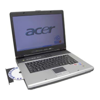
What to do if the Acer Aspire 1640 error still remains after reconnecting the external CD-ROM drive?
- SShannon PerezJul 26, 2025
If the error persists after reconnecting the external CD-ROM drive, try reconnecting the external diskette drive/CD-ROM module. If that doesn't work, replace the external diskette drive/CD-ROM module. As a last resort, replace the main board.