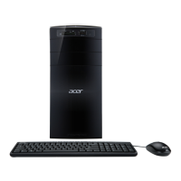
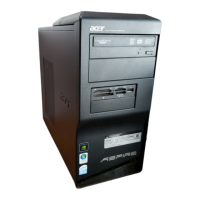
Do you have a question about the Acer Aspire M3800 and is the answer not in the manual?
Lists system features like OS, processor, chipset, memory, PCI, SATA, Audio, LAN, USB, BIOS.
Details processor socket type, type, and FSB.
Specifies the chipset used.
Information on PCB form factor and dimensions.
Details memory support, size, type, slots, and technologies.
Lists PCI Express slot types and quantities.
Details SATA slot type, quantity, and storage support.
Describes audio type, channel, controller, and connectors.
Details LAN controller, speed, and PHY.
Lists USB controller type, ports, and data transfer rate.
Covers BIOS type, size, and boot ROM/FDD detection.
Details I/O controller and rear I/O ports.
Lists specific rear I/O ports like PS/2, VGA, HDMI, LAN.
Lists various connectors on the motherboard.
Details power supply mounting and electrical design features.
Describes chassis compatibility and mounting points for power supply.
Covers wattage, voltage design, connector types, and PFC requirements.
Illustrates the main components and their interconnections.
Identifies components on the computer's front panel.
Identifies ports and components on the computer's rear panel.
Details processor type, socket, FSB, and minimum operating speed.
Covers BIOS code programmer, version, ROM type/size, and boot support.
Lists hotkeys for accessing BIOS setup.
Lists the primary chips on the motherboard.
Shows possible memory configurations and total supported memory.
Details memory slot number, size, type, voltage, and package.
Describes audio controller, channel, compatibility, and connectors.
Details SATA controller, bus, channel count, and bootable CD-ROM support.
Information on the floppy disk drive controller and supported formats.
Details Universal HCI, USB class, and connector quantity.
Specifies operating temperature, humidity, and vibration limits.
Configures system power saving features and states.
Details ACPI support for device standby, global standby, suspend modes, and sleep states.
Describes the process to access the BIOS setup utility.
Displays system details like processor, memory, and BIOS version.
Configures basic system parameters like date, time, and boot options.
Provides access to advanced BIOS features for system configuration.
Allows configuration of advanced chipset features and settings.
Manages settings for onboard peripherals like SATA, USB, and Audio.
Configures system power saving features and ACPI support within BIOS.
Monitors system temperature, fan speeds, and voltages.
Adjusts system frequency and voltage settings for performance.
Manages BIOS passwords for system security.
Resets BIOS settings to factory defaults.
Saves current BIOS settings and exits the setup utility.
Discards changes and exits the BIOS setup utility.
Provides essential information and tools needed before starting disassembly.
Outlines the general steps for disassembling the computer for service.
Details the process for disassembling the front bezel of the Aspire M3800.
Describes the procedure to remove the computer's side cover.
Covers removing the CPU fan pipe and expansion cards.
Steps for removing hard disk drive data cables.
Procedures for removing ODD data/power and HDD power cables.
Steps for removing front panel and USB cables.
Instructions for removing hard disk drives and their brackets.
Procedures for removing the card reader and optical drives.
Details removing motherboard power and fan cables.
Steps to remove the system fan.
Instructions for removing the motherboard from the chassis.
Steps to remove the CPU cooler assembly.
Instructions for removing RAM modules.
Procedure for removing the CPU from its socket.
Steps to remove the rear I/O shielding.
Information on the Power-On Self-Test process.
Key points to check during the POST process.
List of common POST error messages.
Common error symptoms and their potential causes.
Explains how to set jumpers for mainboard configuration.
Details the process for clearing CMOS settings.
Pinout and function of the CPU fan connector.
Pinout and function of system and power fan connectors.
Pinout and function of the ATX 12V power connector.
Pinout and signal names for the ATX 24-pin power connector.
Pinout details for front panel headers, USB, and audio.
Information on intruder detection and other specific headers.
| Tcase | 74.1 °C |
|---|---|
| Bus type | FSB |
| Stepping | R0 |
| Processor cache | 1 MB |
| Processor cores | 2 |
| System bus rate | - GT/s |
| Processor family | Intel® Celeron® |
| Processor series | Intel Celeron Processor E3000 Series for Desktop |
| Processor socket | LGA 775 (Socket T) |
| Processor codename | Wolfdale |
| Processor frequency | 2.5 GHz |
| Processor cache type | L2 |
| Processor lithography | 45 nm |
| Processor manufacturer | Intel |
| Processor front side bus | 800 MHz |
| Processor operating modes | 32-bit |
| ECC supported by processor | No |
| Thermal Design Power (TDP) | 65 W |
| Number of processors installed | 1 |
| CPU multiplier (bus/core ratio) | 12.5 |
| External drive bays | 2x 5.25\ |
| Internal drive bays | 3x 3.5\ |
| Networking features | Gigabit Ethernet |
| Internal memory | 4 GB |
| Internal memory type | DDR3-SDRAM |
| Maximum internal memory | 8 GB |
| Memory layout (slots x size) | - GB |
| HDD interface | SATA |
| Optical drive type | DVD Super Multi |
| Card reader integrated | Yes |
| Total storage capacity | 640 GB |
| Compatible memory cards | CF, Memory Stick (MS), miniSD, MMC, MS PRO, MS PRO Duo, SD, SDHC, xD |
| Discrete graphics card model | Intel® GMA 4500 |
| Audio system | High Definition Audio |
| Product type | PC |
| Audio output channels | 7.1 channels |
| Trial software | Microsoft Office 2007 McAfee Internet Security Suite |
| Bundled software | Acer eRecovery Management Acer Arcade Deluxe Microsoft Works 8.5 eSobi Adobe Reader CyberLink PowerDirector 4 DE CyberLink MediaShow DEX MyWinLocker NTI Media Maker |
| Operating system installed | Windows 7 Home Premium |
| Headphone outputs | 6 |
| USB 2.0 ports quantity | 8 |
| Firewire (IEEE 1394) ports | 0 |
| Ethernet LAN data rates | 10, 100, 1000 Mbit/s |
| Certification | FCC, CE, BSMI, CCC, Nemko, CB, Bauart |
| Power supply | 250 W |
| Chassis type | Tower |
| Product color | Black |
| Processor code | SLGU4 |
| Processor ARK ID | 42771 |
| Depth | 417.6 mm |
|---|---|
| Width | 180 mm |
| Height | 375.5 mm |

