Do you have a question about the Acer Aspire V3-551G and is the answer not in the manual?
| Operating System | Windows 8 |
|---|---|
| Weight | 2.6 kg (5.73 lbs) |
| Processor | AMD A10-4600M |
| Display | 15.6" HD (1366x768) LED-backlit TFT LCD |
| RAM | 4GB DDR3 |
| Storage | 500GB HDD |
| Battery | 6-cell Li-ion |
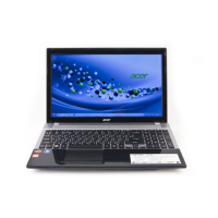
Identifies components on the laptop's exterior, covering top, front, left, right, and base views.
Identifies components on the laptop's top surface.
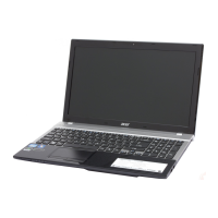
Identifies components on the laptop's front edge.
Identifies ports and connectors on the laptop's left side.
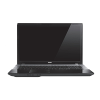
Identifies ports and features on the laptop's right side.
Identifies components located on the laptop's bottom panel.
Summarizes the computer's key features and specifications.
Visual representation of the laptop's internal architecture and components.
Detailed technical specifications for computer components and performance.
Guides users through configuring system hardware and settings via BIOS.
Displays summary of computer hardware information.
Allows setting system time, date, and boot options.
Configures user and HDD passwords for system protection.
Configures the order of boot devices for system startup.
Procedures for updating the system BIOS.
Updates system BIOS using DOS mode utilities.
Updates system BIOS using Windows-based utilities.
Covers unlocking HDD and clearing BIOS passwords.
Procedure to unlock a hard disk drive with a password.
Resets BIOS and password check by clearing CMOS.
Guides for system recovery using crisis utilities.
Guide to create a bootable USB for BIOS recovery.
Diagram showing jumpers and connectors on the mainboard's top side.
Diagram showing components on the mainboard's bottom side.
Location and function of the CMOS clear jumper.
General procedures and guidelines for troubleshooting computer problems.
Steps to diagnose and resolve issues when the system does not power on.
Troubleshooting steps for systems that do not display video output.
Procedure to diagnose and fix issues with the LCD screen display.
Steps to troubleshoot problems with the laptop's built-in keyboard.
Procedure to diagnose and fix problems with the internal speakers.
Troubleshooting steps for problems encountered with USB ports.
Procedure to diagnose and resolve issues with wireless connectivity.
Troubleshooting common BIOS-related issues.
Instructions for resetting a forgotten BIOS password.
Troubleshooting steps for intermittent loss of BIOS settings.
Initial steps and precautions before performing maintenance procedures.
Step-by-step guide to remove the laptop's battery pack.
Step-by-step guide to install the laptop's battery pack.
Procedure to remove the laptop's bottom access panel.
Procedure to remove the Optical Disk Drive module.
Procedure to remove the Dual In-line Memory Module.
Procedure to remove the Hard Disk Drive module.
Procedure to remove the Wireless Local Area Network module.
Procedure to remove the laptop's palm rest assembly.
Procedure to remove the laptop's upper case assembly.
Procedure to remove the laptop's main logic board.
Procedure to remove the CPU thermal module and fan.
Procedure to remove the Central Processing Unit.
Procedure to remove the laptop's internal speakers.
Procedure to remove the laptop's Liquid Crystal Display module.
Procedure to remove the DC power input cable.
Procedure to remove the bezel surrounding the LCD screen.
Procedure to remove the camera module.
Procedure to remove the LCD panel itself from the bezel.
Procedure to remove the Wireless antenna cables.
Procedure to remove the internal microphone module.
Exploded view showing components of the main laptop assembly.
Exploded view of the laptop's lower case assembly.
Exploded view of the laptop's upper case assembly.
Exploded view of the laptop's LCD screen assembly.
Comprehensive list of field-replaceable units with part numbers.
List of screws used in the laptop assembly with their specifications.
Lists components tested and verified in Windows 7.
Describes available online technical support services and resources.