Do you have a question about the Acer Aspire V3-571 and is the answer not in the manual?
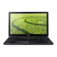
Summary of the computer's key features.
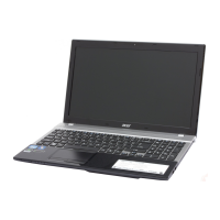
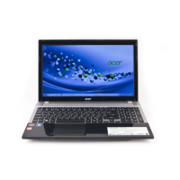
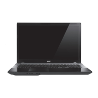
Visual guide to identify laptop components and ports.
Identifies and describes components on the laptop's top surface.
Identifies and describes components on the laptop's front.
Identifies and describes ports and vents on the laptop's left side.
Identifies and describes ports and features on the laptop's right side.
Identifies and describes components on the laptop's bottom.
Explains touchpad operation and gestures.
Describes special keys and function key combinations.
Illustrates the system's internal hardware architecture and connections.
Comprehensive list of the computer's technical specifications.
Overview of the diagnostic utilities available on the system.
Utility for configuring system hardware settings via BIOS.
Guide to navigating BIOS menus and options.
Displays summary of the computer's hardware information.
Allows setting system time, date, and boot options.
Configures advanced hardware settings and peripherals.
Manages system passwords for unauthorized access prevention.
Configures system power management options.
Sets the order of boot devices.
Options to save or discard changes and exit BIOS setup.
Allows selecting boot device without entering BIOS setup.
Procedures for updating the system BIOS Flash ROM.
Details on unlocking HDD and removing BIOS passwords.
Information on using system utilities like DMITools.
Standard operating procedure for creating a crisis USB flash disk.
General information about notebook maintenance procedures and tools.
Lists the tools required for performing maintenance on the notebook.
Graphic representation of module removal and installation sequences.
Preliminary steps before performing any maintenance procedures.
Step-by-step guide to remove the laptop's battery pack.
Step-by-step guide to install the laptop's battery pack.
Procedure to remove the dummy card from its slot.
Procedure to install the dummy card into its slot.
Steps to remove the laptop's base cover.
Steps to install the laptop's base cover.
Procedure to remove the Optical Disc Drive (ODD) module.
Procedure to install the Optical Disc Drive (ODD) module.
Steps to remove the Dual-In-line Memory Module (DIMM).
Steps to install the Dual-In-line Memory Module (DIMM).
General procedures for troubleshooting computer problems.
Troubleshooting steps for when the system does not power on.
Troubleshooting steps for when the system does not display video.
Troubleshooting steps if the LCD picture fails.
Troubleshooting steps for internal keyboard malfunctions.
Troubleshooting steps for touchpad malfunctions.
Troubleshooting steps for internal speaker issues.
Troubleshooting steps for internal microphone issues.
Troubleshooting steps for USB port failures.
Troubleshooting steps for wireless connectivity problems.
Troubleshooting steps for Bluetooth connectivity issues.
Troubleshooting steps for the 4-in-1 card reader.
Troubleshooting steps for issues related to unit thermal performance.
Troubleshooting steps for cosmetic issues with the laptop.
Troubleshooting for other system functions like LAN or HDMI.
Troubleshooting for issues related to BIOS settings or corruption.
Troubleshooting steps for problems that occur sporadically.
Procedures to isolate the cause of undetermined system issues.
Overview of jumper and connector locations on the system board.
Diagram showing jumpers and connectors on the mainboard's top side.
Diagram showing jumpers and connectors on the mainboard's bottom side.
Diagram illustrating the USB board layout and connectors.
Diagram showing the power board components and connectors.
Location and function of the CMOS jumper for clearing settings.
Comprehensive list of field-replaceable units for the system.
Visual breakdown of the main assemblies for parts identification.
Exploded view of the main laptop assembly and its components.
Exploded view of the lower case assembly and its parts.
Exploded view of the upper case assembly and its components.
Exploded view of the LCD module and its constituent parts.
Detailed list of all field-replaceable units with part numbers.
List of screw types and sizes used in the laptop assembly.
Information on compatibility testing for system components.
Details of compatibility tests performed under Windows 7.
Information on accessing online technical support services for Acer systems.
Describes the online technical support services available to users.
| Bus type | DMI |
|---|---|
| Stepping | J1 |
| Tjunction | 100 °C |
| Processor cache | 3 MB |
| Processor cores | 2 |
| Processor model | i5-2450M |
| System bus rate | 5 GT/s |
| Processor family | Intel® Core™ i5 |
| Processor series | Intel Core i5-2400 Mobile Series |
| Processor socket | - |
| Processor threads | 4 |
| Processor codename | Sandy Bridge |
| Processor frequency | 2.5 GHz |
| Processor cache type | Smart Cache |
| Processor lithography | 32 nm |
| Processor manufacturer | Intel |
| Processor front side bus | - MHz |
| PCI Express slots version | 2.0 |
| Processor boost frequency | 3.1 GHz |
| Processor operating modes | 64-bit |
| ECC supported by processor | No |
| PCI Express configurations | 1x16, 2x8, 1x8+2x4 |
| Thermal Design Power (TDP) | 35 W |
| CPU multiplier (bus/core ratio) | 25 |
| Maximum number of PCI Express lanes | 16 |
| Motherboard chipset | Intel HM77 Express |
| Memory slots | 2x SO-DIMM |
| Internal memory | 6 GB |
| Internal memory type | DDR3-SDRAM |
| Maximum internal memory | 8 GB |
| HDD speed | 5400 RPM |
| Storage media | HDD |
| Optical drive type | DVD Super Multi |
| Card reader integrated | Yes |
| Total storage capacity | 500 GB |
| Compatible memory cards | Memory Stick (MS), MMC, xD |
| Number of HDDs installed | 1 |
| Display diagonal | 15.6 \ |
| Display resolution | - pixels |
| Wireless technology | Wi-Fi |
| Disc types supported | CD, CD-R, CD-RW, DVD, DVD+R, DVD+RW, DVD-R, DVD-RW |
| Ethernet interface type | Gigabit Ethernet |
| On-board graphics card ID | 0x116 |
| Discrete graphics card model | Not available |
| On-board graphics card model | Intel® HD Graphics 3000 |
| On-board graphics card family | Intel® HD Graphics |
| On-board graphics card base frequency | 650 MHz |
| On-board graphics card dynamic frequency (max) | 1300 MHz |
| Wi-Fi standards | 802.11b, 802.11g, Wi-Fi 4 (802.11n) |
| Bluetooth version | 4.0 |
| Top Wi-Fi standard | Wi-Fi 4 (802.11n) |
| Ethernet LAN data rates | 10, 100, 1000 Mbit/s |
| Charging port type | DC-in jack |
| USB 2.0 ports quantity | 3 |
| eSATA/USB 2.0 ports quantity | 0 |
| Keyboard layout | QWERTY |
| Pointing device | Touchpad |
| Keyboard language | English |
| Operating system installed | Windows 7 Home Premium |
| Form factor | Clamshell |
| Product color | Black |
| Battery capacity | 4400 mAh |
| Battery life (max) | 4.50 h |
| Number of battery cells | 6 |
| AC adapter power | 65 W |
| Cable lock slot type | Kensington |
| Password protection type | BIOS |
| Cables included | AC |
| Processor code | SR04Z |
| Processor ARK ID | 53452 |
| Processor package size | 37.5x37.5 (rPGA988B); 31 x 24 (BGA1023) mm |
| Supported instruction sets | AVX |
| Intel Identity Protection Technology version | 1.00 |
| Weight | - g |
|---|